 |
 |
Satish Lele satish.lele@gmail.com |
View this page as YouTube Video Presentation
To create a 3D Model, first you have to create concenptual 2D Pipe Routing. Generaly one pipe line is drawn on one layer. This helps in segragating pipe lines. 3D Model package offers tools to create different layers as per line number through a dialog box.3D Model Program also offers facility draw on that line number (3D Model Program sets the line number as current layer). In a concenptual 2D drawing, all the pipe lines are drawn at z cordinate 0. Pipe center line elevations are marked on each horizontal pipe line. This gives idea about layout in plan view.
2D drawing can be converted in 3D Pipe Routing, by lifting the horizontal pipe lines to the elevations of the center line of that pipe line. This can be done by move command. If the centerline elevation is 5000 mm, select the line, select any point as first point and indicate second point as @0,0,5000. In plan view no change will be visible, but line will be visible in 3D isometric view. To see the effect, through view pull down menu, select 3D view and then SW Isometric (or any one of the 4 options). In 3D view, the horizontal pipe lines will be seen at different Z co-ordinates. These can be joined by vertical lines by joining end point of top horizontal pipe line to end point of bottom horizontal pipe line. When one line routing in 3D is completed, the text indicating centerline elevation is erased and line can be frozen, to avoid confusion.
Most inexpensive CAD program like BricksCAD Lite, ProgeCAD, IntelliCAD, Draftsight, CADLogic are prepared in such a manner that these can be easily customized. 4 Programs of OpenPipe are such customized programs. The 3D Piping Model program is based on LISP / VBA programs and around 3000 symbols or blocks are created (with insulation) as and when required and then inserted. The pipe line is cut in that portion. Since blocks are created when required, there is a lot of saving of Disk space. The different piping entities can be arranged on different layers. This is a icon menu driven program. Special Dialogue Boxes are created to make the The 3D Piping Model program more user friendly.
To try 3D Piping Model program, download trial package. 3D Piping Model program is a zip file, 3dpipe_trial.zip. There is no setup.exe file as in other packages. Download and unzip 3dpipe_trial.zip and copy files in a folder. While running inexpensive CAD program like BricksCAD Lite, ProgeCAD, IntelliCAD, Draftsight, CADLogic, click on tools ->Options (or Preferences) -> Files -> + of Support File Search Path -> Add -> Browse -> Select the folder. All files from zip file should be in this folder. |
Triclover package Bought so far by 15 parties
Package for ASME (ANSI) Standard Fittings.
The 3dpipe.zip file contains all program files. There is no setup.exe file as in other packages. Package can not run in AutoCAD LT. Add A line Number: To create 3D Piping Model, first enter line numbers. Click on Add a Line Number. When you click on this, a dialog box opens and shows the line numbers (names of layers) existing in the drawing, if any. You can add a new line number in the text box below. Program creates a new layer with that name. Enter a new line number in text box and press OK. The line number will be added to the list. Add any number of line numbers. After all line numbers are added, press Cancel. The dialog box will disappear. (You can edit or delete line numbers). Auto PipeLine : This asks you to select a pipe. After selecting pipe, Program draws the 3D Pipe Lines with insulation for all pipes on that layer of this size. Use this option after all the fittings are inserted. Lift Pipe : This lifts the pipe line. If the elevation of the pipeline you have drawn is that of bottom of pipe, this option lifts the line to centerline elevation of pipe. Program first asks for UCS. For horizontal lines, select top UCS. Program then asks to select pipe NB, and lifts the pipe up by half the outside diameter of the pipe. Cut Pipe : You can cut a part of the pipe using this option. First select pipeline and then select two points to cut line in between. Elbow : You can insert 90 Deg and 45 Deg Elbows with this option. Select the type and size of the Elbow, insulation thickness and then two lines to insert the elbow. Select proper rotation. The Program also cuts the pipe in elbow portion. 90 Degree Elbow : There are 3 options : 45 Degree Elbow : There are 3 options: Equal Tee : Select the type and size of the Equal Tee and insulation thickness and then select point on main pipe, then on side pipe. Select proper rotation. The Program also cuts the pipe. There are 3 options: Screwed : The are three ratings available. 2000#, 3000# and 6000#. You can draw Screwed Tee for sizes from 8 mm NB to 100 mm NB for all ratings. Screwed : The are three ratings available. 2000#, 3000# and 6000#. You can draw Screwed Cross for sizes from 8 mm NB to 100 mm NB for all ratings. Eccentric Reducer Flat Up : There is only one options You can draw Butt Welded Eccentric Reducer with insulation Flat Up for sizes from 20X10 mm NB to 600X500 mm NB. To insert eccentric reducer, select pipe line on smaller side of the eccentric reducer, then a point on smaller side of eccentric reducer and then insertion point of larger side of eccentric reducer. Select proper rotation. An eccentric reducer with flat side up is inserted. The Program also cuts the pipe. Line Connectors: These connect one pipe to another. In this there are 4 options. Flanges, Full Coupling, Gaskets and Stub Ends. Structural
Wall : To draw a wall, you need architectural drawing like this. Write: You can write in drawing the following. Program asks to select line and then second point to write the text and writes the text. A donut is put on line.
Change : You can change the following: Elevation, Text, Colour to Red, Yellow, Green, Cyan, Blue, Magenta, White
To run program, unzip 3dpipe.zip and copy all files in a folder, say 3dpipe. To set up program, while running AutoCAD program, at command prompt type _options (or _preferences) and press
To set up menu for the program, while running AutoCAD program, at command prompt type menuload and press <enter>. Menu Configuration Dialog box will open. Click on Menu Groups tab. Next to text box File Name, click on browse. Click on down arrow of Files of type box, and select Menu Template (*.mnu). Select either pipe3d_mm or pipe3d_inch, and click on open, Click on Load. For Continue loading MNU file?, click yes. Menu will be compiled and appear in menu groups. Click on Menu Bar Tab, and select either 3dpipe_mm or 3dpipe_inch. In left side Menu Box, 3dpipe menu will appear. In Menu Bar box, click on windows, and click Insert to load 3d menu. Start using Pull Down Menu.
In BricksCAD Lite, installation is bit different. You can add menu with CUSTOMIZE command and You can load lisp file by APPLOAD command.
OR
Load Program: To load 3D Piping program, at command prompt, open trial.dwg and type (load "3p") and press <enter> or use APPLOAD command. It will display Loading 3D Piping Program... Loaded. Type sp3d and press <enter>. 
Program will be start and it will ask for units to be used.
Line Number : This has 3 options.
 Edit A line Number : When you click on this, a dialog box opens and shows the line numbers (names of layers) existing in the drawing, if any. You can select the line number to be edited from the list and type a new line number in the text box below. Program renames that with a new name.
 Delete A line Number : When you click on this, a dialog box opens and shows the line numbers (names of layers) existing in the drawing, if any. You can select the line number to be deleted from the list and line number and layer is deleted from the drawing, if line number and layer is not in use.
 Draw on Line: Select the line you want to draw by selecting its line number and press OK. A message will appear on command line.
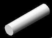
Using Line command, create a Single Line in 3D with proper elevations. The line is set on a layer having layer name as line number. Once single line is created, insert pipe fittings. In each case a block is created by the program and inserted at the insertion point. Create all pipes at the end using AutoPipe option (or individually as one pipe at a time)
 Create Pipe: You can select pipe size from menu from 15mm NB to 1200 mm NB. On screen Program asks to select pipe line, and draws the 3D Pipe Line with insulation. Use this option after all the fittings are inserted.
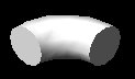
 Butt Welded : You can draw Butt Welded Elbow for sizes from 15 mm NB to 1200 mm NB for Long Radius Elbow and from 15 mm NB to 1200 mm NB for Short Radius Elbow
 Socket Welded : The are three ratings available. 3000#, 6000# and 9000#. You can draw Socket Welded Elbow for sizes from 8 mm NB to 100 mm NB for 3000#, 8 mm NB to 50 mm NB for 6000# and 15 mm NB to 50 mm NB for 9000#.
Screwed : The are three ratings available. 2000#, 3000# and 6000#. You can draw Screwed Elbow for sizes from 8 mm NB to 100 mm NB
Butt Welded : You can draw Butt Welded Elbow for sizes from 15 mm NB to 1200 mm NB
Socket Welded : The are three ratings available. 2000#, 3000# and 6000#. You can draw Socket Welded Elbow for sizes from 8 mm NB to 100 mm NB for 3000#, 8 mm NB to 50 mm NB for 6000# and 15 mm NB to 50 mm NB for 9000#.
Screwed : The are three ratings available. 3000#, 6000# and 9000#. You can draw Screwed Elbow for sizes from 8 mm NB to 100 mm NB for all ratings.
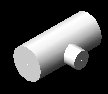
 Branch : You can draw Equal Tee, Reducing Tee, Cross, Weldolet, Full Coupling, Half Coupling, Threadolet, Socolet and Elbolet.
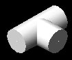
 Butt Welded : You can draw Butt Welded Tee for sizes from 15 mm NB to 600 mm NB.
 Socket Welded : The are three ratings available. 3000#, 6000# and 9000#. You can draw Socket Welded Tee for sizes from 8 mm NB to 100 mm NB for 3000#. You can draw Socket Welded Tee for sizes from 8 mm NB to 50 mm NB for 6000#. You can draw Socket Welded Tee for sizes from 15 mm NB to 50 mm NB for 9000#.
 Reducing Tee: Select the type and size of the Reducing Tee and then select point on main pipe, then on side pipe. Select proper rotation. The Program also cuts the pipe. There is only one options You can draw Butt Welded Reducing Tee for sizes from 20X15 mm NB to 1200X1150 mm NB
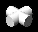
 Cross: Select the type and size of the Equal Cross and then select point on one pipe, then on other pipe. Select proper rotation. The Program also cuts the pipe. There are 3 options:
 Butt Welded : You can draw Butt Welded Cross for sizes from 15 mm NB to 600 mm NB.
 Socket Welded : The are three ratings available. 3000#, 6000# and 9000#. You can draw Socket Welded Cross for sizes from 8 mm NB to 100 mm NB for 3000#. You can draw Socket Welded Cross for sizes from 8 mm NB to 50 mm NB for 6000#. You can draw Socket Welded Cross for sizes from 15 mm NB to 50 mm NB for 9000#.
 Weldolet : Select the size of the Weldolet, insulation thickness and then select point on main pipe, then on side pipe. Select proper rotation. The Program also cuts the pipe. There is only one options You can draw Butt Welded Weldolet for sizes from 20X15 mm NB to 600X500 mm NB.

 Half Coupling : Select the rating and size of the Half Coupling and insulation thickness. Select the NB size of main pipe and then select point on main pipe, then on side pipe. Select proper rotation. The half coupling is inserted on the outer face of pipe. The Program also cuts the side pipe. There are 2 options :
Socket Welded: The are two ratings available. 3000#, 6000#, and 9000#. You can draw Socket Welded Half Coupling for sizes from 8 mm NB to 100 mm NB for 3000#. You can draw Socket Welded Half Coupling for sizes from 8 mm NB to 50 mm NB for 6000#. You can draw Socket Welded Half Coupling for sizes from 15 mm NB to 50 mm NB for 9000#. Screwed: The are two ratings available. 3000# and 6000#. You can draw Screwed Half Coupling for sizes from 9 mm NB to 100 mm NB for both ratings.
Half Coupling : Select the rating and size of the Half Coupling and insulation thickness. Select the NB size of main pipe and then select point on main pipe, then on side pipe. Select proper rotation. The half coupling is inserted on the outer face of pipe. The Program also cuts the side pipe. There are 2 options :
Socket Welded: The are two ratings available. 3000#, 6000#, and 9000#. You can draw Socket Welded Half Coupling for sizes from 8 mm NB to 100 mm NB for 3000#. You can draw Socket Welded Half Coupling for sizes from 8 mm NB to 50 mm NB for 6000#. You can draw Socket Welded Half Coupling for sizes from 15 mm NB to 50 mm NB for 9000#. Screwed: The are two ratings available. 3000# and 6000#. You can draw Screwed Half Coupling for sizes from 9 mm NB to 100 mm NB for both ratings.
 Threadolet : Select the rating and size of the Threadolet. Select the NB size of main pipe and then select point on main pipe, then on side pipe. Select proper rotation. The threadolet is inserted on the outer face of pipe. The Program also cuts the side pipe. The are two ratings available. 3000# and 6000#. You can draw Threadolet for sizes from 15 mm NB to 50 mm NB.
Socolet : Select the rating and size of the Socolet and insulation thickness. Select the NB size of main pipe and then select point on main pipe, then on side pipe. Select proper rotation. The socolet is inserted on the outer face of pipe. The Program also cuts the side pipe. The are two ratings available. 3000# and 6000#. You can draw Socolet for sizes from 15 mm NB to 50 mm NB.
Elbolet : Select the rating and size of the Elbolet and insulation thickness. Select the NB size of main pipe and then select point on pipe along the elbolet, then on pipe perpendicular to elbolet. Select proper rotation. The elbolet is inserted on the outer face of Elbow. The Program also cuts the side pipe. The are two ratings available. 3000# and 6000#. You can draw Elbolet for sizes from 15 mm NB to 50 mm NB.
 Swage : You can draw Swages for pipe sizes with insulation from 80 to 25 mm NB to 15 to 8 mm NB. To insert a swage, select pipe line on smaller side of the swage, then a point on smaller side of swage and then insertion point of larger side of swage. Select proper rotation. A swage is inserted. The Program also cuts the pipe.
 Reducer : You can insert swage, concentric or eccentric reducers of proper size.
 Concentric Reducer : You can draw Butt Welded Concentric Reducer with insulation for sizes from 20X10 mm NB to 600X500 mm NB. To insert concentric reducer, select pipe line on smaller side of the concentric reducer, then a point on smaller side of concentric reducer and then insertion point of larger side of concentric reducer. Select proper rotation. A concentric reducer is inserted. The Program also cuts the pipe.
 Eccentric Reducer Flat Down : There is only one options You can draw Butt Welded Eccentric Reducer with insulation Flat Down for sizes from 20X10 mm NB to 600X500 mm NB. To insert eccentric reducer, select pipe line on smaller side of the eccentric reducer, then a point on smaller side of eccentric reducer and then insertion point of larger side of eccentric reducer. Select proper rotation. An eccentric reducer with flat side down is inserted. The Program also cuts the pipe.

 Flanges:You can draw Slip on, Weld Neck, Blind, Lap Joint, Gasket, Stub End with this. Select Proper rating of flange and size of flange. Select pipeline, a points on pipe at the back of flange and then insertion point of flange (or gasket and stub end) to insert flange (or gasket and stub end). The Program also cuts the pipe.
 Slip On Flange : There are 3 options of pressure ratings :
150# : You can draw Slip on Flanges for pipe sizes from 15 mm NB to 600 mm NB
300# : You can draw Slip on Flanges for pipe sizes from 15 mm NB to 600 mm NB
600# : You can draw Slip on Flanges for pipe sizes from 15 mm NB to 600 mm NB.
 Weld Neck Flange : There are 3 options of pressure ratings :
150# : You can draw Weld Neck Flanges for pipe sizes from 15 mm NB to 600 mm NB
300# : You can draw Weld Neck Flanges for pipe sizes from 15 mm NB to 600 mm NB
600# : You can draw Weld Neck Flanges for pipe sizes from 15 mm NB to 600 mm NB
 Blind Flange : There are 3 options of pressure ratings :
150# : You can draw Blind Flanges for pipe sizes from 15 mm NB to 600 mm NB
300# : You can draw Blind Flanges for pipe sizes from 15 mm NB to 600 mm NB
600# : You can draw Blind Flanges for pipe sizes from 15 mm NB to 600 mm NB.
 Lap Joint Flange : There is only 1 option :
150# : You can draw Lap Joint Flanges for pipe sizes from 15 mm NB to 600 mm NB.
 Full Coupling : You can draw Full Coupling with insulation with this. Select Proper rating and size and insulation thickness. Select pipeline, a points on pipe at the back of Full Coupling and then insertion point of Full Coupling to insert Full Coupling. The Program also cuts the pipe. There are 2 options. Socket Welded : The are two ratings available. 3000#, 6000# and 9000#. You can draw Socket Welded Full Coupling for sizes from 6 mm NB to 100 mm NB for 8 mm NB to 100 mm NB, for 3000# and 6000# and for sizes from 6 mm NB to 100 mm NB for 15 mm NB to 50 mm NB, for 9000#.
Screwed : The are two ratings available. 3000# and 6000#. You can draw Screwed Full Coupling for sizes from 6 mm NB to 100 mm NB.
Full Coupling : You can draw Full Coupling with insulation with this. Select Proper rating and size and insulation thickness. Select pipeline, a points on pipe at the back of Full Coupling and then insertion point of Full Coupling to insert Full Coupling. The Program also cuts the pipe. There are 2 options. Socket Welded : The are two ratings available. 3000#, 6000# and 9000#. You can draw Socket Welded Full Coupling for sizes from 6 mm NB to 100 mm NB for 8 mm NB to 100 mm NB, for 3000# and 6000# and for sizes from 6 mm NB to 100 mm NB for 15 mm NB to 50 mm NB, for 9000#.
Screwed : The are two ratings available. 3000# and 6000#. You can draw Screwed Full Coupling for sizes from 6 mm NB to 100 mm NB.
 Gasket : You can draw Gaskets for pipe sizes from 15 mm NB to 600 mm NB. Select pipeline, a points on gasket side and then insertion point of gasket to insert gasket. The Program also cuts the pipe.
 Stub End : You can draw Stub Ends with insulation for pipe sizes from 15 mm NB to 600 mm NB. Select pipeline, a points on back side of flange and then insertion point of stub end to insert stub end. The Program also cuts the pipe.
 Valves : You can draw Gate, Globe, Check, Wafer Check, Butterfly, Control, Ball, Plug and Safety with this option. You can select Pipe Diameter for Larger Bore and Smaller Bore.
 Gate Valve: Select proper type and size of valve. Then select pipeline and then insertion point on pipe and Valve is inserted. The Program also cuts the pipe. There are 4 options of pressure ratings:
Flanged : You can draw Flanged Gate Valves for different pipe sizes and ratings from 150# to 2500#.
Butt Welded : You can draw Butt Welded Gate Valves for different pipe sizes and ratings from 150# to 2500#.
Socket welded : You can draw Flanged Gate Valves for small bore pipe sizes and ratings from 800# to 2500#
Gate Valve: Select proper type and size of valve. Then select pipeline and then insertion point on pipe and Valve is inserted. The Program also cuts the pipe. There are 4 options of pressure ratings:
Flanged : You can draw Flanged Gate Valves for different pipe sizes and ratings from 150# to 2500#.
Butt Welded : You can draw Butt Welded Gate Valves for different pipe sizes and ratings from 150# to 2500#.
Socket welded : You can draw Flanged Gate Valves for small bore pipe sizes and ratings from 800# to 2500#
 Globe Valve : Select proper type and size of valve. Then select pipeline and then insertion point on pipe and Valve is inserted. The Program also cuts the pipe. There are 3 options: Flanged : You can draw Flanged Globe Valves for different pipe sizes and ratings from 150# to 2500#. Butt Welded : You can draw Butt Welded Globe Valves for different pipe sizes and ratings from 150# to 2500#. Socket welded : You can draw Flanged Globe Valves for small bore pipe sizes and ratings from 800# to 2500#.
 Check Valve : Select proper type and size of valve. Then select pipeline and then insertion point on pipe and point in the direction of flow. Valve is inserted. The Program also cuts the pipe. There are 4 options of pressure ratings : Flanged : You can draw Flanged Check Valves for different pipe sizes and ratings from 150# to 2500#. Butt Welded : You can draw Butt Welded Check Valves for different pipe sizes and ratings from 150# to 2500#. Socket welded : You can draw Flanged Check Valves for small bore pipe sizes and ratings from 800# to 2500#.

 Check Valve : Select proper type and size of valve. Then select pipeline and then insertion point on pipe and point in the direction of flow. Valve is inserted. The Program also cuts the pipe. There are 3 options of pressure ratings: 150# : You can draw Wafer Check Valves for pipe sizes from 150 mm NB to 600 mm NB. 300# : You can draw Wafer Check Valves for pipe sizes from 150 mm NB to 600 mm NB. 600# : You can draw Wafer Check Valves for pipe sizes from 150 mm NB to 600 mm NB.
 Butterfly Valve : Select proper type and size of valve. Then select pipeline and then insertion point on pipe and Valve is inserted. The Program also cuts the pipe. There are 2 options of pressure ratings :
Flanged : You can draw Butterfly Valves for pipe sizes from 80 mm NB to 600 mm NB. Wafer : You can draw Butterfly Valves for pipe sizes from 50 mm NB to 500 mm NB.
 Control Valve : Select proper type and size of valve. Then select pipeline and then insertion point on pipe and Valve is inserted. The Program also cuts the pipe. There are 2 options of pressure ratings and End Connections: 300# : You can draw Flanged Control Valves for pipe sizes from 15 mm NB to 200 mm NB. 600# : You can draw Flanged Control Valves for pipe sizes from 15 mm NB to 200 mm NB. 300# : You can draw Butt Welded Control Valves for pipe sizes from 15 mm NB to 200 mm NB. 600# : You can draw Butt Welded Control Valves for pipe sizes from 15 mm NB to 200 mm NB.
 Ball Valve : Select proper type and size of valve. Then select pipeline and then insertion point on pipe and Valve is inserted. The Program also cuts the pipe. There are 8 options :
End Entry 3 Piece 150# Flanged : You can draw Ball Valves for pipe sizes from 15 mm NB to 150 mm NB
End Entry 3 Piece 300# Flanged : You can draw Ball Valves for pipe sizes from 15 mm NB to 150 mm NB
End Entry 2 Piece 150# Flanged : You can draw Ball Valves for pipe sizes from 40 mm NB to 200 mm NB
End Entry 2 Piece 300# Flanged : You can draw Ball Valves for pipe sizes from 40 mm NB to 200 mm NB
Top Entry 2 Piece 150# Flanged : You can draw Ball Valves for pipe sizes from 150 mm NB to 500 mm NB
Top Entry 2 Piece 300# Flanged : You can draw Ball Valves for pipe sizes from 150 mm NB to 500 mm NB
End Entry 3 Piece Screwed Full Bore : You can draw Ball Valves for pipe sizes from 15 mm NB to 50 mm NB
End Entry 3 Piece Screwed Reduced Bore : You can draw Ball Valves for pipe sizes from 15 mm NB to 50 mm NB
 Plug Valve : Select proper type and size of valve. Then select pipeline and then insertion point on pipe and Valve is inserted. The Program also cuts the pipe. There are 4 options of pressure ratings and end connections:
150# : You can draw Flanged Plug Valves for pipe sizes from 25 mm NB to 300 mm NB.
300# : You can draw Flanged Plug Valves for pipe sizes from 15 mm NB to 200 mm NB.
600# : You can draw Flanged Plug Valves for pipe sizes from 25 mm NB to 250 mm NB.
900# : You can draw Flanged Plug Valves for pipe sizes from 25 mm NB to 250 mm NB.
150# : You can draw Butt Weld Plug Valves for pipe sizes from 25 mm NB to 300 mm NB.
300# : You can draw Butt Weld Plug Valves for pipe sizes from 15 mm NB to 200 mm NB.
600# : You can draw Butt Weld Plug Valves for pipe sizes from 25 mm NB to 250 mm NB.
900# : You can draw Butt Weld Plug Valves for pipe sizes from 25 mm NB to 250 mm NB.
 Safety Valve : Select proper type and size of valve. Then select first pipeline and then second pipeline and insertion point (intersection of these two pipelines). Select rotation angle and Valve is inserted. The Program also cuts the pipe. You can draw safety valves of sizes from 25X25 to 200X250 mm NB.
 Vessel : This displays a Dialog Box, which asks for Shell Diameter, Tan to Tan Length, and then type of head. Program then asks for UCS and draws the vessel.
 Using this in 3D view, or in top (plan) view, you can construct a wall. Program asks you to select first corner point of wall, and then the second corner point. Select opposite end point of wall near the two columns. Program then asks for height of wall. If there is a door in the wall, answer Y to the question, Doors in Wall?. Program asks you to select first corner point of door, and then the second corner point. Select opposite end point of door. Give height of the door. If you want draw door pane, say Y to Door Frame?. Program asks you to select first corner point of door frame, and then the second corner point. Select opposite end point of door pane inside the door frame. Program draws the box for door, which is then subtracted from the wall box. If windows are present, say Y to windows in wall? Enter number of windows present. Program asks you to select first corner point of window, and then the second corner point. Select opposite end point of window. Enter elevation of window from the floor, and then height of window frame. Program draws the box for window, which is then subtracted from the wall box. If you want draw window pane, say Y to Window Pane?. Program asks you to select first corner point of window pane, and then the second corner point. Select opposite end point of window pane inside the window frame. Wall is drawn with door and windows.
 Utilities : There are a number of utilities options.
 Set UCS : You can set the UCS to top, left, right, front, back, bottom etc.
Elevation in mm Elevation, TOS Elevation, CL Elevation, FOF Elevation, NRV Elevation, BOP Elevation Elevation in meter Elevation, TOS Elevation, CL Elevation, FOF Elevation, NRV Elevation, BOP Elevation Line Number Line Number with elevation in Meters, in mm Hold Support No-1 Line Support No-2 Lines Comment
Pipe Gap : You can get the gap between two pipelines based on the pipe diameter and flange rating.
Test Pressure : You can calculate Hydrostatic or Air Test Pressure for a pipeline.Steel Sections:
US Standard : Beam, Channel, Angle and Tee
Indian Standard : Beam, Channel, Angle and Tee
International : Beam, Channel, Angle, Square and Rectangle


Fitting Name : You can get description of a fitting and its name using this options. Select fitting and fitting will be shown.
Insert Existing Fitting : You can insert an already inserted (existing) fitting at new location. Select fitting and follow instructions.
Insert Flange and Gasket : You can insert a flange and gasket near a valve. Select valve and follow instructions. (You will also be asked to insert stub end for 150# lap joint flange).
Bill of Material : You can get Bill of Material of all entities in the model. Program gives BOM for every line as Length of pipe, fittings with quantity. Bill of Material is the written to a MS Excel file. This is written in VBA. When Program loads Program asks about macro. Select Enable macros option.
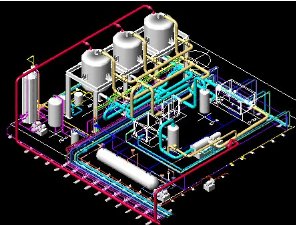
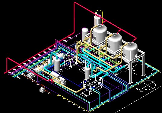
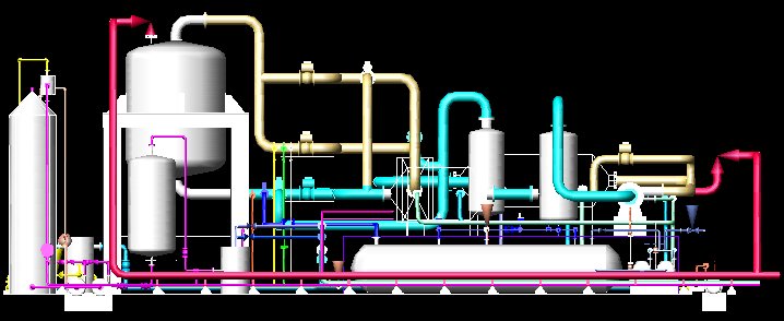
Complete 3D Engineering Scale Model from South West Side
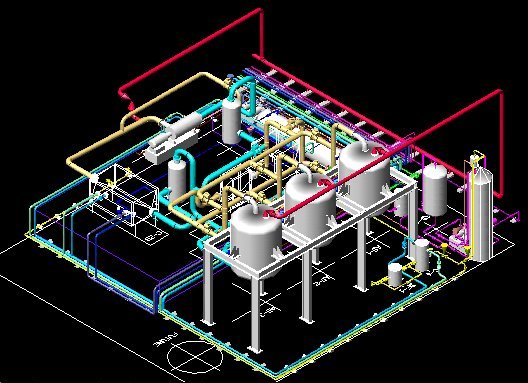
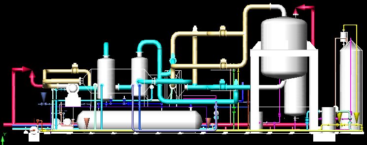
Complete 3D Engineering Scale Model from South East Side
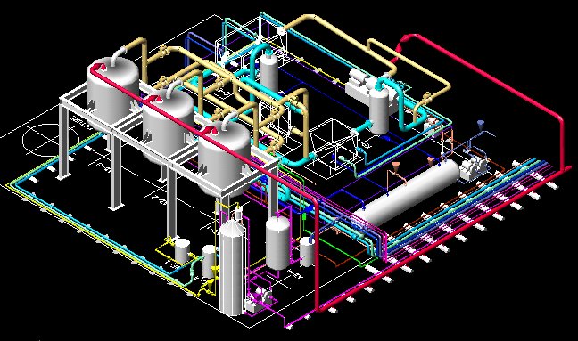
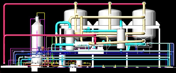
Complete 3D Engineering Scale Model from North East Side
Complete 3D Engineering Scale Model from North West Side
Complete 3D Engineering Scale Model from Top
Complete 3D Engineering Scale Model from Left Side
Complete 3D Engineering Scale Model from Right Side
Complete 3D Engineering Scale Model from Front Side
Complete 3D Engineering Scale Model from Back Side
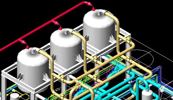
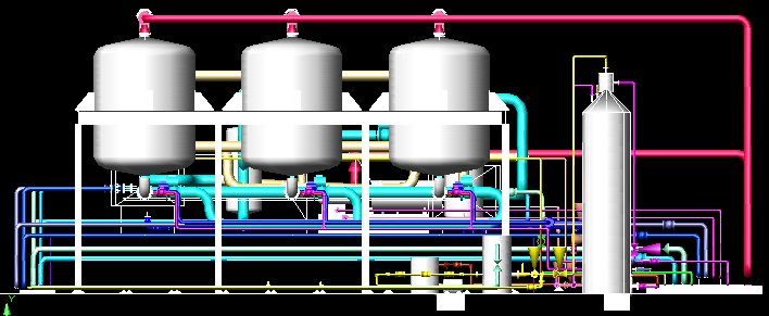
Close-up of 3 Dryers
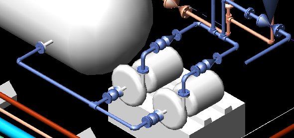
Pump and associated Piping along Sump Tank
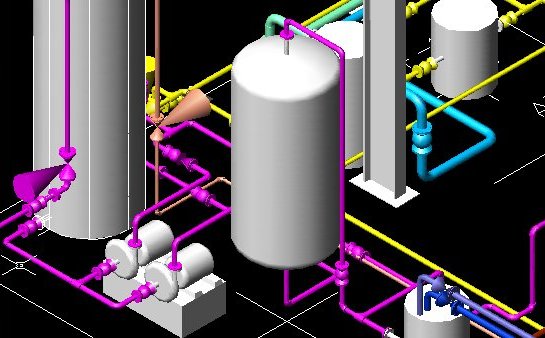
Pump and associated Piping near Feed Tank
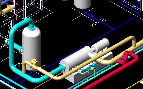
Compressor and associated Piping
Battery Limit End for Piping

Individual fittings in the Model

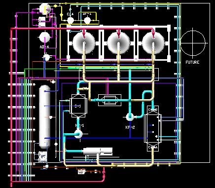
 2D Piping
