 |
Satish Lele lelepiping@gmail.com |
View this page as YouTube Video Presentation
- Piping Plan:
- Routing: Basically, yard piping is desirable to be assembled in one area on sleepers, for economic efficiency, safety, ease of construction, operability, and maintenance and inspection, and to be planned in the shortest possible route by also preventing pipes from crossing each other. Following are the general notes with respect to the routing.
- Yard piping shall have its routing laid out along the oil dikes or roads as much as possible.
- An overall routing plan shall be made in consideration of spacing for electrical instrumentation ducts, trenches and fire fighting piping, etc.
- Piping other than those connected to tanks shall not have its routing pass through the area surrounded by oil dikes.
- Routing shall be planned by keeping the road crossing areas as least as possible.
- Pump suction lines shall be routed to minimize pressure drop caused by piping configuration.
- Lines having process requirements (requirements for the gravity flow and slope of lines such as for flare, blow-down, and condensate) shall be planned at a higher priority.
- A minimum distance of 0.5 m shall be secured from the dike or the fence to the support or the piping.
- Location: In order to set the location of the primary pipe support systems the total plant layout must be established. This means that all the various disciplines must have a very good idea what equipment is required and it's size. The "Plot Plan" must be reviewed by all the key people on the project and then approved by the client.
- Configuration: This is the selection of "fit-for-purpose." Each main run, minor run and branch run must be looked at to determine its configuration. Will it be an overhead rack or a sleeper way? Will each be single deck (layer) or multiple deck? Will the support be a single column ("T") support or multi-column support? How many columns? A second part of the configuration issue effects pipe racks in the process units themselves. This is the question of whether or not the pipe rack will support equipment such as Air Coolers (Fin Fans). Another part of configuration is the issue of intersections. Poor planning on this issue can cause problems later with the piping.
- Height: How high should each run of rack be? Should they be elevated or low sleepers. The sleepers are concrete with an imbedded steel plate on the top. For sleepers, they need to be off the ground to allow for maintenance and drainage also to prevent corrosion. For elevated multi-level racks what should the separation be? For elevated racks you must plan the height and the separation of the whole system together. A key element in the determination of separation is the line sizes to be carried on the racks.
- Width: This requires a detailed study of the total piping systems for the whole plant based on pipe rack routing. In the past, a study (called a "Transposition") was done to, as best you could, account for each line on each pipe rack. From this study, a berth sequence was established and the line spacing set. A percentage was added as an error factor and then the clients "future" reserve was added. This then constituted the minimum rack width. The final width would be set after all racks were "sized" and then some might be rounded up in width for consistency, based on the materials of construction/fabrication method.
- Spacing: This issue can be addressed after the transposition has been completed. The transposition identifies all the rack piping from the largest to the smallest From this the average line size for each leg of the rack system can be established. With the pipe size information (largest, smallest and average pipe size) the number and spacing of the pipe support bents can be set. A cost tradeoff is evaluated and made between more pipe supports spaced closer together or fewer pipe supports and some sort of intermediate support system.
- Materials of construction / fabrication method: What materials are the pipe racks to be made of and what will be the fabrication method? Pipe racks can be bare steel, steel with a concrete encasement (fireproofing), reinforced concrete or a combination. The steel can be steel structural shapes or pipe shape. The concrete fireproofing can be cast in place onto (or around) the steel columns and beams or it can be pre-cast onto the columns and beams prior to installation. The reinforced concrete pipe supports can also be cast in place or pre-cast then field erected. The space requirement for a reinforced concrete column or beam is about twice that of bare steel.
- Special Lines: Sloping lines may be supported on the side of rack. Piping carrying caustic materials, chemicals, acids or similar services shall not be located near equipment or other piping with service temperatures exceeding 95oC and where avoidable should not be run over escape routes. Piping smaller than 50 mm NB shall not be run in pipe racks or sleeper ways. Where pipe sizes on racks require a support spacing which is less than the bent spacing, intermediate support beams shall be installed. Generally, small piping shall not be supported from larger piping. On sleeper ways, sleepers shall be spaced to suit the pipe requiring the smallest support span, but should not be spaced less than 3000 mm apart. Hot insulated lines should be grouped together and separated from cold lines.
- Routing: Basically, yard piping is desirable to be assembled in one area on sleepers, for economic efficiency, safety, ease of construction, operability, and maintenance and inspection, and to be planned in the shortest possible route by also preventing pipes from crossing each other. Following are the general notes with respect to the routing.
- Support Planning:
- Types of support:
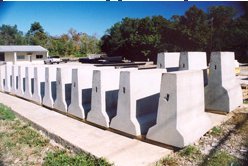
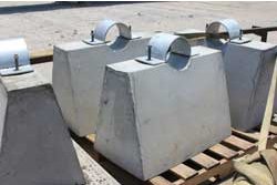
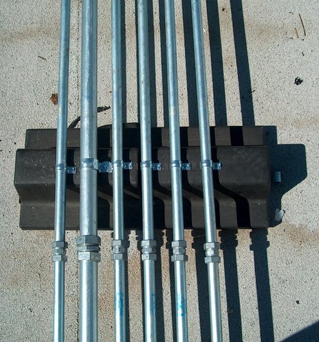
- Sleeper type: Durable, economical and easy to install, the precast concrete pipeline sleepers / supports are the answer to problems associated with metal, wood and cast-in-place concrete pipe sleepers. With the precast concrete pipeline sleeper there is no more corrosion or decay problems. Manufactured of high-strength steel reinforced concrete, the pipeline sleepers are resistant to salt and corrosive environments. With the precast pipeline sleepers, the product is delivered to the jobsite and can be set immediately when required, versus the cast-in-place sleepers which require costly onsite construction, supervision, weather delays and the task of getting ready-mix concrete to the most remote project sites. Onshore piping laid on sleepers at grade shall have minimum clearance of 400mm between bottom of pipe and finished grade.
- Rack type / Multi Level Lines: Whenever possible the Pipe rack shall be single level. On single level pipe racks, process piping shall be placed outsides with utility and service piping on the middle. Where multilevel racks are required, generally process lines shall be placed on the lower rack levels, and utility and service piping shall be placed on the upper rack level. However, draining considerations shall be taken into account when placing process lines on multilevel racks, by applying the following rules of thumb:
1· If both ends of a process line are lower than the lower level, the line should be run in the lower level.
2· Process lines that connect two nozzles elevated higher than the top level should be located in the top level.
3· Process lines having one end lower than the lower level can run in either the lower or upper level.
Specific elevations shall be established and maintained for lines running the north / south direction, and different elevations for lines running east / west. North / south and east / west pipe racks shall intersect midway between deck levels. At every change of direction the piping should change elevation, but care should be taken to minimize pockets.
- Electrical and Instrument Cable Trays: These will normally be run in or off the side of the pipe racks. Piping Designers shall liaise with these disciplines to allocate these areas. Cable trays systems shall be kept away from hot lines. It shall be determined by considering the following items: Width, Spacing, Elevation and Locations of supports for guide and stopper
- Sleeper type: Durable, economical and easy to install, the precast concrete pipeline sleepers / supports are the answer to problems associated with metal, wood and cast-in-place concrete pipe sleepers. With the precast concrete pipeline sleeper there is no more corrosion or decay problems. Manufactured of high-strength steel reinforced concrete, the pipeline sleepers are resistant to salt and corrosive environments. With the precast pipeline sleepers, the product is delivered to the jobsite and can be set immediately when required, versus the cast-in-place sleepers which require costly onsite construction, supervision, weather delays and the task of getting ready-mix concrete to the most remote project sites. Onshore piping laid on sleepers at grade shall have minimum clearance of 400mm between bottom of pipe and finished grade.
Continuous Pipe racks (conventional pipe rack) system: This is essentially a system where multiple 2-dimensional (2D) frame assemblies (commonly called bents), comprised of two or more columns with transverse beams, are tied together in the longitudinal direction utilizing beam struts (for support of transverse pipe and raceway elements and for longitudinal stability of the system) and vertical bracing to form a 3D space frame arrangement.
Pipe racks supporting equipment such as air-cooled heat exchangers must utilize the continuous system approach. - Types of support:
- Plot plans and equipment location plans.
- 3D model showing piping layout, cable tray layout, Pipe rack bent spacing and elevation of support levels in the transverse direction, Elevation of longitudinal beam struts and locations of vertical bracing. and location of pipe bridge, if any.
- Piping orthographic drawings.
- Vendor prints of equipment located on the rack, e.g., air coolers and exchangers. The vendor prints should include the equipment layout, mounting locations and details, access and maintenance requirements, and the magnitude and direction of loads being transmitted to the pipe rack.
- Electrical and control systems drawings showing the routing and location of electrical and instrumentation raceways and/or supports.
- Underground drawings that show the locations of buried pipes, concrete structures and foundations, duct banks, etc. in the area of the pipe rack.
- Pipe rack construction material (Steel, Cast-in-situ concrete, Pre-cast concrete) shall be as per project design criteria.
- Detailed Arrangement:
- Type of Yard Piping: Process Piping, Drain Oil, Off-Gas Piping, Utility Piping and Others.
- Arrangement:
- Piping arrangement shall be planned by grouping process and utility respectively.
- Small diameter piping shall be arranged in one area to allow easier support.
- Electrical and instrumentation ducts shall be arranged at the end of supports to allow easier check and maintenance.
- When horizontal loop is required in gravity flow piping such as flare, condensate lines, etc., such piping shall be arranged at the end of supports.
- Others:
- Road Crossing: In general, equipment layout shall be prepared considering straight pipe rack, however other shapes like L/T/U/H/Z etc can also be considered based on area available. The total width of pipe rack shall include 30% extra space or 1.5m (min) for future modifications in unit at later stage at all levels/tiers. The width of the rack shall be 6m, 8m or 10m for single bay and 12M, 16M or 20M for double bay having 4 tiers maximum. For interconnecting pipes to different units, existing pipe racks to be expanded wherever possible considering foundation and column design. The spacing between pipe rack portals shall be taken as 6m in general. However it can be changed to suit intra unit’s distances. Each bay between two passing columns shall have secondary structural members at a span of 3 meters to enable supporting of small bore lines. Pipe racks shall be fireproofed, with provision of insert plates in supporting auxiliaries. Clearance beneath pipe rack shall be 4.5 meters minimum. Road Clearance shall be 9m minimum for main road. Secondary road clearance shall be 5 meters. 20 mm diameter rod is provided above Pipe rack to be made of CS. Corrosion wear pads shall be provided for all the lines at support locations.
- Drain Piping: Whenever possible, the main should be installed with a fall of not less than 1:100 (1 m fall for every 100 m run), in the direction of the steam flow. This slope will ensure that gravity, as well as the flow of steam, will assist in moving the condensate towards drain points where the condensate may be safely and effectively removed.
The drain point must ensure that the condensate can reach the steam trap. Careful consideration must therefore be given to the design and location of drain points. Consideration must also be given to condensate remaining in a steam main at shutdown, when steam flow ceases. Gravity will ensure that the water (condensate) will run along sloping pipe work and collect at low points in the system. Steam traps should therefore be fitted to these low points. The amount of condensate formed in a large steam main under start-up conditions is sufficient to require the provision of drain points at intervals of 30 meters to 50 meters, as well as natural low points such as at the bottom of rising pipe work. In normal operation, steam may flow along the main at speeds of up to 145 km/h, dragging condensate along with it. Figure shows a 15 mm drain pipe connected directly to the bottom of a main.
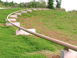
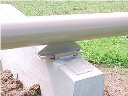
- Piping at Sloped Site: This is like drain piping on flat land. Unlike level lands, flow velocities and pressure can buildup in systems on sloping land. This can pose substantial hazards to the system and to the land.
Data collection for pipe rack design: Due to the fast track nature associated with most of the projects, often the final piping, raceway, and equipment information is not available at initiation of the pipe rack design. Therefore, as a Civil/Structural Engineer, you should coordinate with the Piping group, Electrical, Control Systems, and Mechanical groups to obtain as much preliminary information as possible. When received, all design information should be documented for future reference and verification. In the initial design, the Engineer should use judgment when applying or allowing for loads that are not known, justifying them in the design basis under Design Philosophy (a part of your calculation). The following should be reviewed for design information:
 to get all the information as a eBook
