 |
Satish Lele lelepiping@gmail.com |
View this page as YouTube Video Presentation
These are storage tanks between units, and can serve a variety of purposes. They can dampen fluctuations in flow rate, composition or temperature. They can allow one unit to be shut down for maintenance without shutting down the entire plant. The surge drum performs various important functions. They are:FLASH DRUMS

Flash drums is a vessel into which flow a mixture of liquid and vapor. The goal is to separate the vapor and liquid. For design calculations it is normally assumed that the vapor and liquid are in equilibrium with one another and that the vessel is adiabatic (no heat lost or gained). One must simultaneously satisfy a material balance, a heat balance, and equilibrium.
FLARE LINES

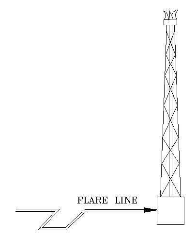
Flare is a means of safe disposal of waste gases by combustion. With an
elevated flare, the combustion is carried out at the top of a pipe or stack where
the burner and igniter are located. A ground flare is similarly equipped, except
combustion is carried out at or near ground level. A burn pit differs from a flare in that it is primarily designed to handle liquids. Flare Blow Off/Flame Lift-up is the lifting of flame front from the flare tip. Flare Blow Out is the extinguishing of flare flame. Open Disposal System is a disposal system that discharges directly from the relieving device to the atmosphere with no containment other than a short tail pipe.

Selection of Blow down Systems: While the various systems for the disposal of voluntary or involuntary vapor or liquid are available, the actual selection of a disposal system is conducted in accordance with the expected frequency, duration of operation, required capacity and fluid properties.
Blow down System for Vapor Relief Stream: Systems for the disposal for voluntary and involuntary vapor discharges are:
- To atmosphere
- To lower pressure process vessel or system
- To closed pressure relief system and flare
- Acid gas flare
1. Vapor discharge to atmosphere: Vapor relief streams shall be vented directly to atmosphere if all of the following conditions are satisfied (as per API RP 521):
a. Such disposal is not in conflict with the present regulations concerning pollution and noise.
b. The vapor is effectively non-toxic and non-corrosive.
c. Vapor which is lighter than air or vapor of any molecular mass that is nonflammable, non-hazardous and non-condensable.
d. There is no risk of condensation of flammable or corrosive materials.
e. There is no chance of simultaneous release of liquid, apart from water.
f. Relief of flammable hydrocarbons direct to the atmosphere should be restricted to cases where it can be assured that they will be diluted with air to below the lower flammable limit. This should occur well before they can come in contact with any source of ignition.
The above condition can most easily be met if the vapors to be released have a density less than that of air. However, with proper design of the relief vent adequate dilution with air can be obtained in certain cases with higher density vapors. Methods of calculation are given in API RP 521 section 4.3.
a. Vapor from depressurizing valves shall be discharged to a closed pressure relief system.
b. Vapor which contains 1% H2S or more by volume, shall be discharged to a closed pressure relief system.
2. Vapor discharge to lower pressure process vessel or system:
Individual safety/relief valves may discharge to a lower pressure process system or vessel capable of handling the discharge.
Although this type is rarely used, it is effective for discharges that contain materials which must be recovered.
3. Vapor discharge to closed pressure relief system and flare: In all cases where the atmospheric discharge or release of vapor to a lower pressure system is not permissible or practicable, vapor shall be collected in a closed pressure relief system which terminates in a flare, namely flare system. Where the concentration of H2S is such that condensation of acid gas is probable, provision for a separate line, heat traced, shall be considered. In all cases, the installation of a closed pressure relief system shall result in a minimum of air pollution and the release of combustion products.
4. Acid gas flare: In process plants where H2S free and H2S containing streams are to be flared, consideration should be given to the installation of a separate header and flare stack assembly for the H2S containing streams. The following provisions should be studied for the acid gas flare assembly:
a. Automatic injection of fuel gas down stream of H2S pot in order to make the combustion stable.
b. Steam injection for smokeless operation shall not be considered for H2S flare tip.
c. A common pilot igniter may be used to ignite all flare stacks including the acid flare.
d. The H2S flare header and sub headers may be heat traced in order to prevent the condensation acid gas.
Blow down System for Liquid Relief Stream: Systems for the disposal of voluntary and involuntary liquid discharges are:
- To onsite liquid blow down drum.
- To lower pressure process vessel or system.
- To oily water sewers only if the material will not cause hazardous conditions.
- To pump suction if pump will not overheat or can withstand the expected temperature rise.
- To burning pit.
- To vaporizer.
Thermal expansion relief valves may discharge small quantities of volatile liquid or vapor into the atmosphere, provided the valve outlet is in a safe location.
1. Liquid discharge to onsite liquid blow down drum The liquid shall be discharged to an onsite liquid blow down drum which is capable of retaining the liquid discharged at the required liquid relief rate for a period of 20 minutes. This drum shall have a vapor discharge line to the closed pressure relief system.
2. Liquid discharge to lower pressure process vessel or system The liquid shall be discharged to a lower pressure process vessel or system which is capable of handling the required liquid relief rate plus any flashed vapor.
3. Liquid discharge to oily water sewer Liquid discharge to an oily water sewer shall be nonvolatile and nontoxic. The required liquid relief rate shall be within the oil removal capability of the oily water treating system.
4. Liquid discharge to pump suction Required liquid relief shall discharge to an upstream liquid reservoir from which the pump takes suction. The liquid relief may discharge directly to the pump suction line if sufficient cooling is provided to prevent a temperature rise of the liquid recycled through the pump when the safety/relief valve opens or when a constant displacement pump is used.
5. Liquid discharge to burning pit Liquid relief or voluntary liquid blow down which need not be returned to the process or discharged to an oily water sewer, shall be discharged to a burning pit, if environmentally accepted.
6. Liquid discharge to vaporizer The liquid shall be discharged to a vaporizer which is capable of vaporizing a liquid relief of no more than 5,000 kg/h.
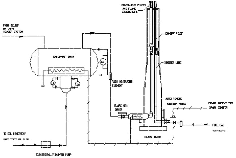
Design of Disposal System Components: Depending on the process plant under consideration, a disposal system could consists of a combination of the following items: piping, knock-out drum, quench drum, seal drum, flare stack, ignition system, flare tip, and burning pit.
Piping:
Standards used:
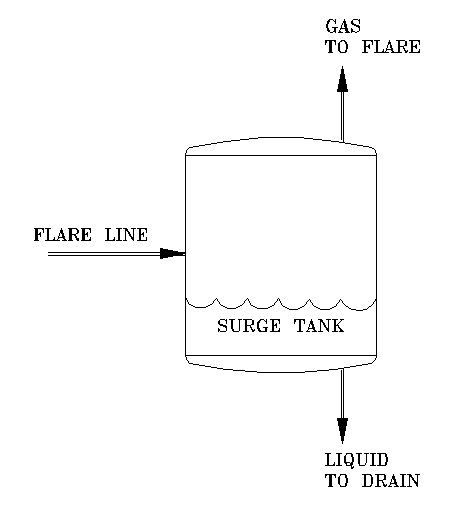
To separate the liquid out of the gas and allow the gas to pass to the flare line, to drain the liquid from the flare line.
To absorb surges in the flare line as it may occur due to variation of load during operation. When the load becomes heavier and duty is greater, more gas is formed and less liquid may be carried in the flare line.
The third function of a surge drum is to absorb the violent liquid surging that occurs when the flare line is quickly opened. The immediate drop in pressure, on the liquid lying in the flare line, creates a tremendous amount of vapor. Practically the entire charge of liquid left in the flare line at shut-down is suddenly thrown up into the surge drum.


Selection of Blow down Systems: While the various systems for the disposal of voluntary or involuntary vapor or liquid are available, the actual selection of a disposal system is conducted in accordance with the expected frequency, duration of operation, required capacity and fluid properties.
Blow down System for Vapor Relief Stream: Systems for the disposal for voluntary and involuntary vapor discharges are:
- To atmosphere
- To lower pressure process vessel or system
- To closed pressure relief system and flare
- Acid gas flare
1. Vapor discharge to atmosphere: Vapor relief streams shall be vented directly to atmosphere if all of the following conditions are satisfied (as per API RP 521):
a. Such disposal is not in conflict with the present regulations concerning pollution and noise.
b. The vapor is effectively non-toxic and non-corrosive.
c. Vapor which is lighter than air or vapor of any molecular mass that is nonflammable, non-hazardous and non-condensable.
d. There is no risk of condensation of flammable or corrosive materials.
e. There is no chance of simultaneous release of liquid, apart from water.
f. Relief of flammable hydrocarbons direct to the atmosphere should be restricted to cases where it can be assured that they will be diluted with air to below the lower flammable limit. This should occur well before they can come in contact with any source of ignition.
The above condition can most easily be met if the vapors to be released have a density less than that of air. However, with proper design of the relief vent adequate dilution with air can be obtained in certain cases with higher density vapors. Methods of calculation are given in API RP 521 section 4.3.
a. Vapor from depressurizing valves shall be discharged to a closed pressure relief system.
b. Vapor which contains 1% H2S or more by volume, shall be discharged to a closed pressure relief system.
2. Vapor discharge to lower pressure process vessel or system:
Individual safety/relief valves may discharge to a lower pressure process system or vessel capable of handling the discharge.
Although this type is rarely used, it is effective for discharges that contain materials which must be recovered.
3. Vapor discharge to closed pressure relief system and flare: In all cases where the atmospheric discharge or release of vapor to a lower pressure system is not permissible or practicable, vapor shall be collected in a closed pressure relief system which terminates in a flare, namely flare system. Where the concentration of H2S is such that condensation of acid gas is probable, provision for a separate line, heat traced, shall be considered. In all cases, the installation of a closed pressure relief system shall result in a minimum of air pollution and the release of combustion products.
4. Acid gas flare: In process plants where H2S free and H2S containing streams are to be flared, consideration should be given to the installation of a separate header and flare stack assembly for the H2S containing streams. The following provisions should be studied for the acid gas flare assembly:
a. Automatic injection of fuel gas down stream of H2S pot in order to make the combustion stable.
b. Steam injection for smokeless operation shall not be considered for H2S flare tip.
c. A common pilot igniter may be used to ignite all flare stacks including the acid flare.
d. The H2S flare header and sub headers may be heat traced in order to prevent the condensation acid gas.
Blow down System for Liquid Relief Stream: Systems for the disposal of voluntary and involuntary liquid discharges are:
- To onsite liquid blow down drum.
- To lower pressure process vessel or system.
- To oily water sewers only if the material will not cause hazardous conditions.
- To pump suction if pump will not overheat or can withstand the expected temperature rise.
- To burning pit.
- To vaporizer.
Thermal expansion relief valves may discharge small quantities of volatile liquid or vapor into the atmosphere, provided the valve outlet is in a safe location.
1. Liquid discharge to onsite liquid blow down drum The liquid shall be discharged to an onsite liquid blow down drum which is capable of retaining the liquid discharged at the required liquid relief rate for a period of 20 minutes. This drum shall have a vapor discharge line to the closed pressure relief system.
2. Liquid discharge to lower pressure process vessel or system The liquid shall be discharged to a lower pressure process vessel or system which is capable of handling the required liquid relief rate plus any flashed vapor.
3. Liquid discharge to oily water sewer Liquid discharge to an oily water sewer shall be nonvolatile and nontoxic. The required liquid relief rate shall be within the oil removal capability of the oily water treating system.
4. Liquid discharge to pump suction Required liquid relief shall discharge to an upstream liquid reservoir from which the pump takes suction. The liquid relief may discharge directly to the pump suction line if sufficient cooling is provided to prevent a temperature rise of the liquid recycled through the pump when the safety/relief valve opens or when a constant displacement pump is used.
5. Liquid discharge to burning pit Liquid relief or voluntary liquid blow down which need not be returned to the process or discharged to an oily water sewer, shall be discharged to a burning pit, if environmentally accepted.
6. Liquid discharge to vaporizer The liquid shall be discharged to a vaporizer which is capable of vaporizing a liquid relief of no more than 5,000 kg/h.
Design of Disposal System Components: Depending on the process plant under consideration, a disposal system could consists of a combination of the following items: piping, knock-out drum, quench drum, seal drum, flare stack, ignition system, flare tip, and burning pit.
Piping:
- In general, the design of disposal piping should conform to the requirements of ASME B31.3 Installation details should conform to those specified in API Recommended Practice 520, Part II.
- Inlet piping: The design of inlet piping should be in accordance with API-RP-521, Section 5.4.1.2.
- Discharge piping: The sizing should be in accordance with API-RP-521, Section 5.4.1.3 in conjunction with Appendix A as a supplement to the above.
- Liquid blow down header: In order to reduce relief header loads and prevent surges due to two-phase gas/liquid flow as much as possible, it is advisable to direct all disposable liquids into a separate blow down network. In determination of back pressure the following shall be taken into consideration:
- Flashing of liquid at relief/safety valve discharge or along the network due to pressure drop and/or warm-up to ambient temperatures should be analyzed.
- Solids formation due to auto refrigeration and presence of high melting point liquids should be determined.
- If flashing and auto refrigeration is possible, a temperature profile along the network should be established so that proper piping material selection and construction practices is undertaken.
- The network should be self-draining and should not include pockets.
- The network should be continuously purged by natural gas controlled through an orifice.
- High liquid velocities should be watched for within the network.
- Stress: The design should be in accordance with ASME B.31.3 Chapter II, Part 2,302.3.5.
- Anchors, guides, and supports: The design should be in accordance with API-RP-521; and ASME B.31.3 Chapter II, Part 5, 321.2.
- Drainage: Disposal system piping should be self-draining toward the discharge end. Pocketing of discharge lines should be avoided. Where pressure relief valves handle viscous materials or materials that can solidify as they cool to ambient temperature, the discharge line should be heat traced. A small drain pot or drip leg may be necessary at low points in lines that can not be sloped continuously to the knockout or blow down drum. The use of traps or other devices with operating mechanisms should be avoided.
- Details
- Safety/relief valve connection to the header: Normally, the laterals from individual relieving devices should enter a header from above.
- Safety/relief valves connection when installed below the relief header Laterals leading from individual valves located at an elevation above the header should drain to the header. Locating a safety valve below the header elevation in closed systems should be avoided. Laterals from individual valves that must be located below the header should be arranged to rise continuously to the top of the header entry point. However, means should be provided to prevent liquid accumulation on the discharge side of these valves.
Standards used:
- API (American Petroleum Institute)
- API RP 520 "Sizing, Selection and Installation of Pressure-Relieving
Devices in Refineries"
Part I -Sizing and Selection
Part II – Installation - API RP 521 "Guide for Pressure-Relieving and Depressurizing Systems"
- API Publication 931 "API Manual on Disposal of Refinery Wastes, Volume on Atmospheric Emissions".
- API RP 520 "Sizing, Selection and Installation of Pressure-Relieving
Devices in Refineries"
- ASME (American Society of Mechanical Engineers) ASME B 31.3 "Process Piping"
 to get all the information as a eBook
