 |
Satish Lele lelepiping@gmail.com |
View this page as YouTube Video Presentation
- Pumps: A centrifugal pump is a kinetic machine converting mechanical energy into hydraulic energy through centrifugal activity. A centrifugal pump is one of the simplest pieces of equipment. Its purpose is to convert energy of an electric motor or engine into velocity or kinetic energy and then into pressure of a fluid that is being pumped. The energy changes occur into two main parts of the pump, the impeller and the volute. The impeller is the rotating part that converts driver energy into the kinetic energy. The volute is the stationary part that converts the kinetic energy into pressure. Liquid enters the pump suction and then the eye of the impeller. When the impeller rotates, it spins the liquid sitting in the cavities between the vanes outward and imparts centrifugal acceleration. As the liquid leaves the eye of the impeller a low pressure area is created at the eye allowing more liquid to enter the pump inlet. Provide temporary conical type strainers in 2 inch or 50 millimeters and larger butt weld pump suction lines for use during startup. Arrange piping to facilitate removal. Use permanent Y-type strainers on 2 inch or 50 millimeters and smaller screwed or socket weld pump suction piping.
- Centrifugal Pumps: A centrifugal pump is a rotary dynamic pump that uses a rotating impeller to increase the pressure of a fluid. Centrifugal pumps are commonly used to move liquids through a piping system. The fluid enters the pump impeller along or near to the rotating axis and is accelerated by the impeller, flowing radially, outward into a diffuser or volute chamber casing, from where it exits into the downstream piping system. Centrifugal pumps are used for large discharge through smaller heads. A centrifugal pump works by converting kinetic energy into potential energy measurable as static fluid pressure at the outlet of the pump. This action is described by Bernoulli's principle. With the mechanical action of an electric motor or similar, the rotation of the pump impeller imparts kinetic energy to the fluid through centrifugal force. The fluid is drawn from the inlet piping into the impeller intake eye and is accelerated outwards through the impeller vanes to the volute and outlet piping. As the fluid exits the impeller, if the outlet piping is too high to allow flow, the fluid kinetic energy is converted into static pressure. If the outlet piping is open at a lower level, the fluid will be released at greater speed.
- Multistage Centrifugal Pumps: A centrifugal pump containing two or more impellers is called a multistage centrifugal pump. The impellers may be mounted on the same shaft or on different shafts. If we need higher pressure at the outlet we can connect impellers in series. If we need a higher flow output we can connect impellers in parallel. All energy added to the fluid comes from the power of the electric or other motor force driving the impeller.
- Vertical Inline Pumps: Vertical Inline Close Coupled Pumps are specifically designed for mounting, in any position, directly in a pipe line. The suction and discharge nozzles are located on the same centerline 180 degrees apart. Vertical pumps significantly reduce the space required, two pumps fit in the space of one. They are easy to maintain; simply remove the cap screws and the motor and bracket assembly is easily removed from the casing without disturbing the piping. The impeller is direct coupled to the motor shaft for easy maintenance to minimize impeller run out and reduce noise. Most pump parts except for the casing, are 100% interchangeable. The inline casing has provisions for mounting an optional support base should the pump sit on the floor. Mechanical seals can be provided as standard to prevent leakage around the shaft. A relief line may be provided from the seal faces to the pump discharge for flushing and venting purposes. Suction Branch Design pre-rotates suction liquid in the direction of pump impeller rotation. This concept minimizes pumping noise that is otherwise associated with more common short radius suction inlet designs.
- Cavitation: Within a centrifugal pump, the flow area at the eye of the pump impeller is usually smaller than either the flow area of the pump suction piping or the flow area through the impeller vanes. When the liquid being pumped enters the eye of a centrifugal pump, the decrease in flow area results in an increase in flow velocity accompanied by a decrease in pressure. The greater the pump flow rate, the greater the pressure drop between the pump suction and the eye of the impeller. If the pressure drop is large enough, or if the temperature is high enough, the pressure drop may be sufficient to cause the liquid to flash to vapor when the local pressure falls below the saturation pressure for the fluid being pumped. Any vapor bubbles formed by the pressure drop at the eye of the impeller are swept along the impeller vanes by the flow of the fluid. When the bubbles enter a region where local pressure is greater than saturation pressure farther out the impeller vane, the vapor bubbles abruptly collapse. This process of the formation and subsequent collapse of vapor bubbles in a pump is called cavitation. Cavitation in a centrifugal pump has a significant effect on pump performance. Cavitation degrades the performance of a pump, resulting in a fluctuating flow rate and discharge pressure. Cavitation can also be destructive to pumps internal components. When a pump cavitates, vapor bubbles form in the low pressure region directly behind the rotating impeller vanes. These vapor bubbles then move toward the oncoming impeller vane, where they collapse and cause a physical shock to the leading edge of the impeller vane. This physical shock creates small pits on the leading edge of the impeller vane. Each individual pit is microscopic in size, but the cumulative effect of millions of these pits formed over a period of hours or days can literally destroy a pump impeller. Cavitation can also cause excessive pump vibration, which could damage pump bearings, wearing rings, and seals. A small number of centrifugal pumps are designed to operate under conditions where cavitation is unavoidable. These pumps must be specially designed and maintained to withstand the small amount of cavitation that occurs during their operation. Most centrifugal pumps are not designed to withstand sustained cavitation. Noise is one of the indications that a centrifugal pump is cavitating. A cavitating pump can sound like a can of marbles being shaken. Other indications that can be observed from a remote operating station are fluctuating discharge pressure, flow rate, and pump motor current.
Pump Curves: It gives the Best Efficiency Point, which is the point at which effects of head or pressure and flow converge to produce the greatest amount of output for the least amount of energy. For a specified impeller diameter and speed, a centrifugal pump has a fixed and predictable performance curve. The point where the pump operates on its curve is dependent upon the characteristics of the system, in which it is operating, commonly called the System Head Curve, or the relationship between flow and hydraulic losses in a system. This representation is in a graphic form and, since friction losses vary as a square of the flow rate, the system curve is parabolic in shape.
STEP 1: The basic pump curves are no different than reading any other head � flow curve. For a known head value, follow the head overto the pump curve then drop down to the capacity axis and this will be the flow rate. What you are trying to figure out here is what diameter impeller is needed to get the required head and capacity.
STEP 2: The next thing to figure out is what motor is needed to drive this impeller without overloading. To do this, use the dashed horse power lines. To the right of the horse power line is overloading and to the left is non-overloading. Selecting an impeller diameter where the line does not cross the dashed HP curve is a non-overloading pump.
STEP 3: The last thing to determine is at what pump efficiency the pump will operate. Look at the U shaped lines and interpolate to get the efficiency.- Pump Location and Layout: If available floor area is limited, a vertical unit generally requires less area. However, if available headroom is limited the horizontal unit almost invariably requires less headroom. It should be kept in mind that area and height requirements will differ somewhat between various manufacturers and with the type of configuration of the unit specified.
- Compressor: A gas compressor is a mechanical device that increases the pressure of a gas by reducing its volume. Compressors are similar to pumps: both increase the pressure on a fluid and both can transport the fluid through a pipe. As gases are compressible, the compressor also reduces the volume of a gas. Liquids are relatively incompressible, so the main action of a pump is to transport liquids.
Reciprocating Compressor: Reciprocating compressors are often some of the most critical and expensive systems at a production facility, and deserve special attention. Gas transmission pipelines, petrochemical plants, refineries and many other industries all depend on this type of equipment. Due to many factors, including but not limited to the quality of the initial specification/design, adequacy of maintenance practices and operational factors, industrial facilities can expect widely varying lifecycle costs and reliability from their own installations.
Various compressors are found in almost every industrial facility. Types of gases compressed include the following:- Air for compressed tool and instrument air systems
- Hydrogen, oxygen, etc. for chemical processing
- Light hydrocarbon fractions in refining
- Various gases for storage or transmission
- Other applications
Reciprocating compressors are typically used where high compression ratios (ratio of discharge to suction pressures) are required per stage without high flow rates, and the process fluid is relatively dry. Wet gas compressors tend to be centrifugal types. High flow, low compression ratio applications are best served by axial flow compressors. Rotary types are primarily specified in compressed air applications, though other types of compressors are also found in air service.
Centrifugal Compressor: A centrifugal compressor is a radial flow rotodynamic fluid machine that uses mostly air as the working fluid and utilizes the mechanical energy imparted to the machine from outside to increase the total internal energy of the fluid mainly in the form of increased static pressure head.
During the second world war most of the gas turbine units used centrifugal compressors. Attention was focused on the simple turbojet units where low power-plant weight was of great importance. Since the war, however, the axial compressors have been developed to the point where it has an appreciably higher isentropic efficiency. Though centrifugal compressors are not that popular today, there is renewed interest in the centrifugal stage, used in conjunction with one or more axial stages, for small turbofan and turboprop aircraft engines.
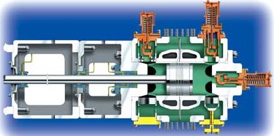
A centrifugal compressor essentially consists of three components.- A stationary casing
- A rotating impeller as shown in Figure which imparts a high velocity to the air. The impeller may be single or double sided, but the fundamental theory is same for both.
- A diffuser consisting of a number of fixed diverging passages in which the air is decelerated with a consequent rise in static pressure.
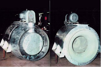
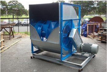
- Fan / Blower:
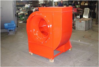
Single Width Single Inlet (SWSI) fans are most commonly used when suction duct is required on the fan inlet. The single width fan has the advantage of providing a connection from the duct straight to the fan inlet, without the use of inlet boxes.
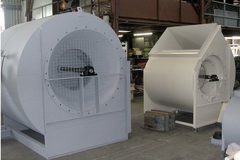
Double Width Double Inlet (DWDI) fans are used primarily in air handling units or in plenum chambers where the connection of the inlet duct directly to the fan is not a requirement.
In-line centrifugal fans combine the performance characteristics of the traditional scroll-type centrifugal fans with the space saving advantages of axial type fans. These fans are applicable for general building ventilation, commercial and industrial installations.
Air Handling Unit (AHU) fans, designed to appeal to fan buyers looking for a less expensive double width, double inlet centrifugal fan option.
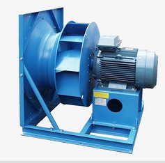
Plug fans are high performance centrifugal impellers that have been designed for clean or slightly dusty air, to achieve the best possible aerodynamic performance when not fitted within a conventional fan housing.
- NPSH (Net Positive Suction Head): The margin of pressure over vapor pressure, at the pump suction nozzle, is Net Positive Suction Head (NPSH). NPSH is the difference between suction pressure (stagnation) and vapor pressure. In equation form:
NPSH = Ps - Pvap
Where:
NPSH = NPSH available from the system, at the pump inlet, with the pump running
Ps = Stagnation suction pressure, at the pump inlet, with the pump running
Pvap = Vapor pressure of the pumpage at inlet temperature
Since vapor pressure is always expressed on the absolute scale, suction pressure must also be in absolute terms. Both pressures must be in psia or kg / sq cm a. Gauge pressure is converted to absolute pressure by adding atmospheric pressure. In equation form:
absolute pressure = gauge pressure + atmospheric pressure
The above equation provides an answer in units of pressure (psi). This can be converted to units of head (feet) by the following equation:
h = 2.31p/SG
Where:
h = Head, feet
p = Pressure, psi
SG = Specific gravity of the liquid
Units of NPSH: For centrifugal pumps, NPSH values are expressed in units of specific energy (equivalent column height) such as feet or meters. For displacement pumps (rotary and reciprocating), NPSH values are normally expressed in pressure units such as pounds per square inch (psi), kilopascals, or bars.
NPSH values are neither gauge pressures nor absolute pressures. The g in psig means that the pressure is measured above atmospheric pressure. The a in psia means that the pressure is measured above absolute zero, a perfect vacuum. NPSH is a measurement of pressure above vapor pressure, so the units of NPSH (in the U.S.) are just psi or feet.
What Symbol Should We Use?: Because units of pressure are typically used to express the value of NPSH for a displacement pump, some authors, and companies, use symbols such as NPIP (for net positive inlet pressure) and NIP (for net inlet pressure), because the units are pressure units, not head units. For simplicity, I'll stick with NPSH, regardless of the units used.
Suction Pressure: The First Half of the NPSH Equation: Suction pressure must be determined at the pump suction nozzle when the pump is running. If suction pressure is measured with a gauge, the atmospheric pressure (at the pump location) must be added to the gauge reading to convert the reading to absolute pressure. The elevation of the gauge must also be added (if the gauge is above datum) or subtracted (if the gauge is below datum). Although often negligible, the velocity head in the pipe at the gauge connection should be added to obtain total (stagnation) pressure. For a reciprocating pump (and some rotaries), the acceleration head must be subtracted. (More on acceleration head later.)
Vapor Pressure: The Second Half of the NPSH Equation: Vapor pressure is more difficult to determine than suction pressure. It is a measure of the "desire" of a liquid to boil to a gas. Some liquids, such as butane and ammonia, have high vapor pressures. They must be kept under pressure, or they will boil (flash). An open container of pure ammonia would quickly boil away, filling the area with noxious ammonia gas.
Cool water has a low vapor pressure. An open container of cool water, on the earth's surface, would not boil, but would evaporate slowly over a period of days. The desire of cool water to boil is therefore low. If we were to place that same open container of cool water on the surface of the moon, it would boil away, similar to the ammonia. Why? The atmospheric pressure on the moon is zero, a perfect vacuum. The vapor pressure of pure, air-free water at 80-deg F is about 1/2-psia. This means that if the pressure on the water is reduced below 1/2- psia, the water will boil.
A Function of Temperature: Vapor pressure is a function only of temperature. As the temperature of the liquid increases, its vapor pressure increases until the critical temperature is reached. At the critical temperature, vapor pressure vanishes. Above the critical temperature, there is no distinction between a liquid and a gas. It is all fluid.
Boiling Reestablishes Equilibrium Conditions: Any liquid at its vapor pressure is on the verge of boiling (flashing). In such a condition it is said to be in equilibrium, at its bubble point or saturated. If the pressure is reduced slightly, it will start to boil. If the temperature is held constant (which requires heat input) and the pressure held constant (below the vapor pressure), the liquid will continue to boil until it has all flashed to vapor.
If heat is not provided to the liquid, the portion flashing to vapor will cool, and will also absorb heat from the remaining liquid, causing the liquid temperature to drop. The lower temperature will result in a lower vapor pressure. The boiling will continue only until the vapor pressure drops to the pressure which is imposed on the liquid. When that vapor pressure is reached, and the boiling stops, the liquid-vapor mixture.
 to get all the information as a eBook
