 |
Satish Lele lelepiping@gmail.com |
View this page as YouTube Video Presentation
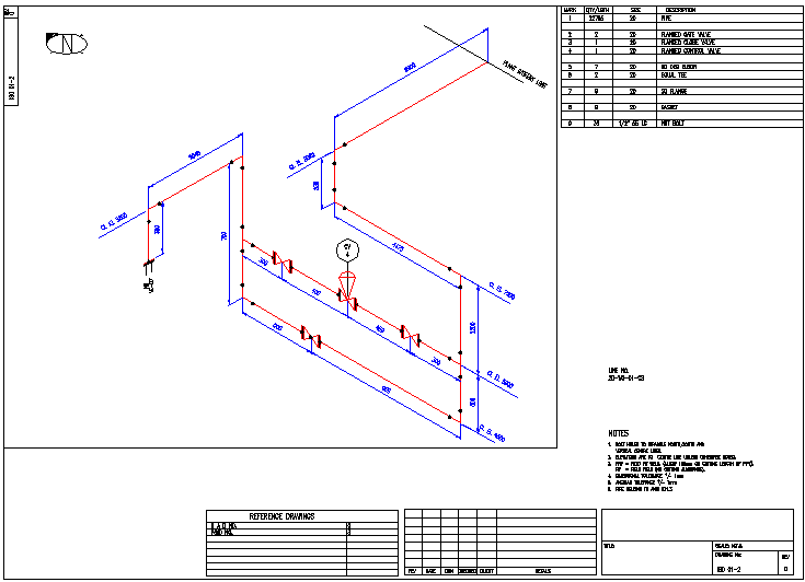
Piping isometrics is 2D representation, of a 3D pipe routine. It is generally printed on a A3 size paper. One pipe line is drawn on one sheet. The line may continue in 2 or more drawings. If two lines are similar, (suction lines of 2 pumps) the two are drawn on one sheet. Isometric drawing is important for a pipe fabricator. He can interpret it along with 2D piping plan, for proper layout. It is easier for him to get exact piping materials required from the store house.
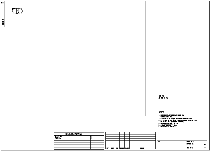
In top left corner, the north direction is shown. It matches with the north direction of the piping plan drawing. The isometric drawing number and revision is also indicated.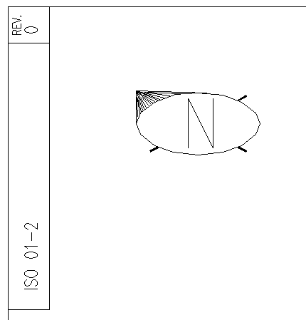
In the lower right corner, title block of company is inserted, which also shows drawing number. Line number and notes are also written above it.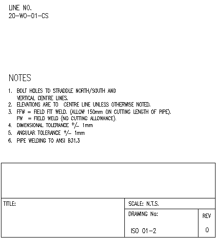
Below the isometrics, reference drawings, and details of drawing revisions is given.
Typical isometric of a line. This drawing shows a control station. All dimensions and elevations are mentioned in the drawing. To draw an isometric, start from one end of pipe. Locate North direction of piping plan and follow proper direction and elevations on piping plan to reach the other end. Horizontal distances are measured on the piping plan and inserted in isometrics. Elevations given in piping plan are written on line. The difference in elevation is the vertical dimension. Indicate both end points of the pipe line. The drawing is not drawn to scale. The pipe length in drawing depends on complexity of that portion of line.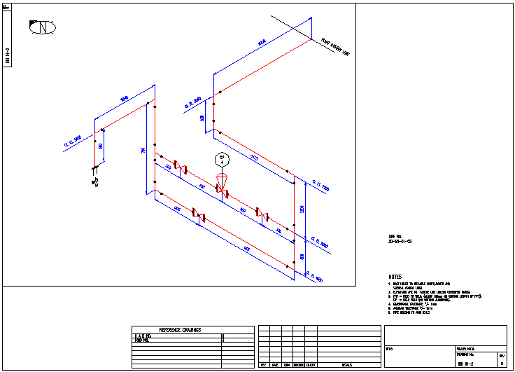
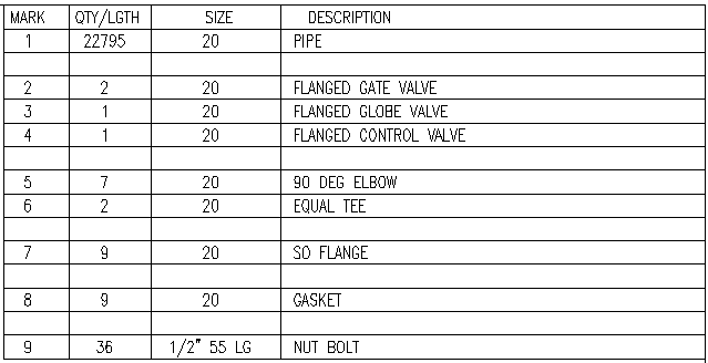
Bill of Material for the Line.
Details of Bill of Material Used.

In top left corner, the north direction is shown. It matches with the north direction of the piping plan drawing. The isometric drawing number and revision is also indicated.

In the lower right corner, title block of company is inserted, which also shows drawing number. Line number and notes are also written above it.

Below the isometrics, reference drawings, and details of drawing revisions is given.

Typical isometric of a line. This drawing shows a control station. All dimensions and elevations are mentioned in the drawing. To draw an isometric, start from one end of pipe. Locate North direction of piping plan and follow proper direction and elevations on piping plan to reach the other end. Horizontal distances are measured on the piping plan and inserted in isometrics. Elevations given in piping plan are written on line. The difference in elevation is the vertical dimension. Indicate both end points of the pipe line. The drawing is not drawn to scale. The pipe length in drawing depends on complexity of that portion of line.

Bill of Material for the Line.

Details of Bill of Material Used.

 to get all the information as a eBook
