Piping is used for Industrial, Marine, Transportation and Plumbing purposes. Industrial piping is used for Process and Utility services. Process piping is used to transport process fluids between storage tanks and process units. Service or Utility piping is used to convey steam, air, water, fuel oil etc. Marine piping is piping inside a ship. It is very complex as space available is limited and shape of hull is tapered. Due to this less volume is availabe as we go down in the ship. Cross country piping is installed for transportation of liquids from one location to another location. It can be above the ground or underground. Oil and gas is transported by underground pipelines with steel pipes coated from outside. Water is transported under the ground by Cast Iron pipes and above the ground with steel pipes installed on saddles. Plumbing is done in residencial areas using Plastic or Galvanized Iron pipes.
 Tubes
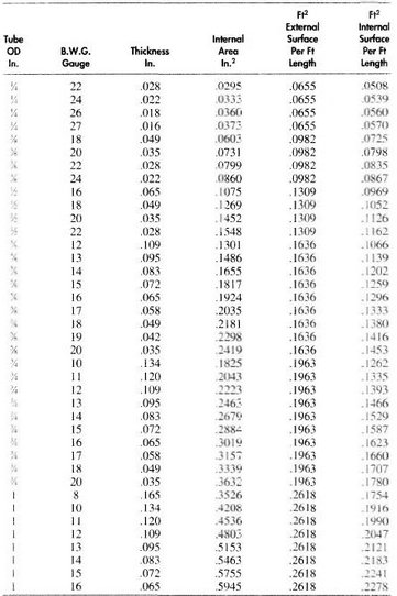
Tubes: Tubes generally have smaller diameter (6 mm NB to 25 mm NB) and are seamless. These are produced by extrusion process. Tubes are not used as pipes but used for steam tracing. These are mostly used in Heat Exchangers. Tube is specified, by outside diameter and wall thickness in mm. The wall thickness is also expressed in BWG (Birmingham Wire Gauge). The principal uses for tube are in heat exchangers, instrument lines, and inter-connections on equipments such as compressors, boilers, and refregerators.
 Pipe
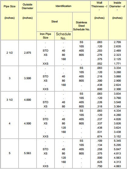
Pipe is identified by Nominal Pipe Size (NB), and wall thickness defined by schedule number, API designations or weights. Non-standard pipes are specified by nominal size (NB) and wall thickness. In DIN Standard, pipe is specified by outside diameter and wall thickness in mm. Pipes are of two types.
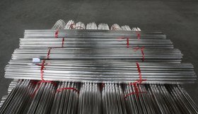
- Seamless: These are produced by piercing a billet in hot metal and are similar to tubes but are of higher diameters than tube. These are used for severe operating conditions (mostly for high pressure and temp services as in case of steam).
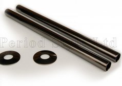
- ERW (Electric Resistance Welded): These are produced as per ASTM A-53B. This general service carbon steel pipe is electrical resistance welded. Pipe of this grade typically has thickness as per Schedule 40 and 80. It is well suited for fabrication, and may be used for pressure vessels with limitations of pressure and temperature. Often used for oil, water, gas and petroleum products.
 SIZES
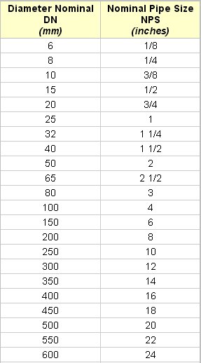
SIZES: The size of all pipes is identified by Nominal Pipe Size (NB, DN, NPS). It is seldom equal to the true bore (internal diameter) of the pipe. Pipes with 350 mm NB and larger sizes have outside diameter equal to nominal pipe size. Normal pipe sizes (NB) as per ASME/ANSI Standard are 15, 20, 25, 40, 50, 80, 100, 150, 200, 250, 300, 350, 400, 450, 500 and 600 mm NB. 32, 65, 95, 125 mm NB pipes are normally used in small length for final connection to equipments, but piping later is done with one larger size.
Pipes having smaller NB than 15 are restricted for instrument lines or for steam services and other lines which have to mate with other equipments. 15 NB pipe is extensively used for steam tracing and auxiliary piping at pump. Pipes with diameter larger than 600 mm NB are defined by Standard of American Water Works Association (AWWA)
 Lengths
: Straight pipe is supplied in random lengths of 6 to 8 meters and double this length.
 Pipe Ends
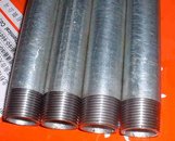
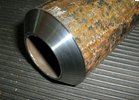
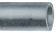
 of these lengths are generally either Plain end (PE) for socket welding or Beveled end (BE) for butt-welding, or threaded (which is supplied with one coupling per length).
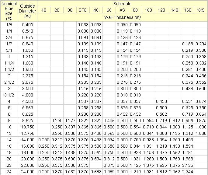
Pipe Thickness: Pipes in the various sizes are made in several wall
thicknesses for each size, which have been established by three different institutions.
- ANSI/ASME specify thickness through schedule numbers, and are specified in ASME Standard B36.10. For stainless steel ASME standard B36.19, establishes a range of thin walled sizes, identified by schedules 5S and 10S.
- ASTM specifies 3 thickness STD:standard, XS:extra-strong and XXS:double extra strong.
- API through its standard 5L and 5LX.
 Temperature and Pressure Limits
: Carbon Steels lose strength at high temperatures. Electric-resistance-welded (ERW) pipe is not considered satisfactory for service above 400
oC. For higher temperatures, pipes made from Stainless Steel or other alloys should be considered.
Material of Construction: Different materials are used for construction of pipes and tubes. These are Carbon Steel, Iron, Non Ferrous, Plastic, Glass, and Lined metal.
- Carbon Steel: The most readily available carbon steel pipe is made to ASTM A53 in schedules 40, 80, STD and XS sizes, in electric arc welded (Grade A and Grade B-the later grade has the higher tensile strength) and in seamless (Grade A and B) constructions.
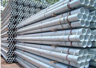
 Common finishes are Black (plain or mill finish) and Galvanized.
Like other Carbon Steels, ASTM A53 has a specific gravity of approximately 7.85, and therefore a density of approximately 7850 kgs/m3. Pipe produced as per ASTM A53 is available with grades A and B. Grade A is commonly used for structural applications. Pipe of ASTM A53 Grade A has a minimum yield strength of 2050 kg/m2, and tensile strength of 3200 kg/m2. ASTM A53 Grade B has a minimum yield strength of 2400 kg/m2, and tensile strength of 4000 kg/m2.
ASTM A106 Grade A has a tensile strength of 3200 kg/m2. ASTM A106 Grade B has a tensile strength of 4000 kg/m2, ASTM A106 Grade C has tensile strength of 4500 kg/m2.
Most sizes and weights are also available in seamless carbon steel to ASTM A 106, which is comparable specification to ASTM A 53 in tensile strength, but prescribing more stringent testing. Three grades of ASTM A 106 are available, Grade A, B and C, in order of increasing tensile strength. Straight seam welded and spiral welded pipe is made from plate and seamless pipe is made by piercing solid billets. Carbon Steel pipe is strong, ductile, weldable, mechineable, reasonably durable and is cheaper than pipe made from other materials. If carbon steel pipe can meet the requirements of pressure, temperature, corrosion resistance and hygiene, it is natural choice.
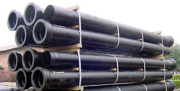
- Iron Pipes: These are made from Cast Iron and Ductile Iron. The principal uses are for water, gas and sewage lines which are laid under the ground. Wrought iron pipe is seldom employed.
- Non-Ferrous Metal Pipes: Pipes or tubes made from copper, lead, nickel, brass, aluminum and various grades stainless steels can be readily obtained. These materials are relatively expensive and are selected usually either because of their particular corrosion resistance to process chemicals, their good heat transfer, or for their tensile strength at higher temperatures.
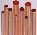 Copper and Copper Alloys These are traditionally used for Instrument air supply lines, Food Processing lines, and in Heat Transfer Equipments. Stainless Steel pipes are now increasingly being used for these purposes.
Temper: Temper denotes the hardness and strength of pipe or tube. Products are available in a variety of tempers like H (Hard), HH (Half Hard), QH (Quarter Hard), O (soft annealed) and OL (light annealed). Straight lengths primarily drawn are commonly known, hard tube. Annealed temper tube is referred to as soft tube. The following points provide the various tempers in which copper and copper alloy pipes, tube and fittings are provided.
Hard Drawn: No visible grain. Used where minimal forming will be performed and maximum strength is required.
Half Hard: 0.015-0.040 mm grain size. This temper is similar to light annealed or light annealed rotary straightened, but has much higher yield strength due to drawing after annealing. This product is used where high rigidity is desired with minimal amount of forming ability.
Light Anneal: 0.015-0.040 mm grain size. Preferred for tight bends and extreme forming application. This is an annealed temper with a fine grain size to prevent orange peel and fracturing when forming.
Soft Anneal: 0.040-0.060 mm grain size. This temper is suitable for general purpose bending and forming which is not as extreme as that requiring light annealed temper. Soft anneal temper hardens at a slower rate than light anneal.
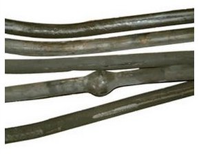 Lead: Primarily used for conveying dilute suphuric acid. Lead Pipe (Seamless) is made from Pure Lead Metal (99.97% min.) or Lead Alloys, which is readily fabricated by extrusion. Lead Metal has excellent property of corrosion resistance and flexibility. Lead Pipes find many uses in the chemical industry. For these applications, lead Pipe is made from either chemically Pure Lead or up to 6% Antimonial Lead Alloy. Pure Lead (Chemical Grade) Pipes & Antimonial Lead Pipes are offered as per client specification. Standard sizes are 10 mm ID (min) and 200 mm ID (max). The main applications for such Lead Pipes are for Water, Soil Waste, Ventilation, Gas, Telephones, Under ground works, Acids & Chemicals. In present time, Lead Pipes are mainly used for carriage of corrosive chemicals in chemical plants. The appropriate composition of Lead with other alloying Metal is extruded for cutting into short length sleeve which is used for joining Lead Sheathed Cables.
 Cupro Nickel: Copper is proven since the early days, to have many good attributes. It was easy to bend and had very high corrosion resistance, but there was concern about its low corrosion-fatigue strength. When copper-nickel was introduced, it displayed corrosion resistance similar to copper, higher general strength and better fatigue strength. Good formability allows ease of flaring and bending, and although the metal cost is greater than that of steel alternatives, copper-nickel is very attractive in view of its extra life, trouble-free installation and safety/reliability characteristics.
Properties of Copper-Nickel Brake Tubing: The copper-nickel alloy used for brake tubing typically contains 10% nickel, 1.4% of manganese and 0.8% of iron respectively. The product conforms to ASTM B466, which specifies dimensions, tensile strength and yield strength. Formability and internal cleanliness conforms to specifications SAE J527 (Society of Automobile Engineers), ASTM A254 and SMMT C5B (Society of Motor Manufacturers and Traders). Also, the alloy meets the requirements for pressure containment, fabrication and corrosion resistance for ISO 4038 (International Standards Organization) and SAE J1047.
Corrosion Resistance: For many years prior to its application as a brake tubing material, alloy C70600 had been used in ships, power station condensers and hydraulic lines on tankers, and had displayed excellent resistance to saline conditions. Early tests revealed that copper-nickel has almost the same resistance to burst pressure as steel. In testing, however, when exposed to salt spray over 180 days, steel's burst strength decreases significantly. The copper alloy remains consistently resistant.
For tubes covered with a moist, salty mudpack for six months, brazed steel was severely corroded resulting in perforation of the tubing wall; whereas, only superficial general corrosion was found on the copper-nickel tubing. ISO 4038 and SAE J1047 include a corrosion resistance requirement referring to ISO 3768 asking for a minimum burst pressure of 110 MPa after 96 hours in neutral salt spray. Swedish requirements include a resistance at least equal to 25� of zinc. In all cases alloy C70600 easily exceeds the required corrosion resistance.
Copper-nickel brake tubing provides superior reliability and assures both manufacturers and vehicle owners improved durability for effective long-life functioning of the brake system.
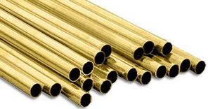 Brass: Using brass pipes has its advantages. Since brass pipe fittings are corrosion resistant and durable, they last longer than other materials. They are also easily manufactured, so you can easily have brass pipes in the size and shape you prefer. Brass pipe suppliers provide various kinds of brass pipe fittings for plumbing business. Some of the most commonly used are: pipe adaptors, pipe couplings, pipe elbows, pipe nipples, pipe unions, pipe tees, pipe plugs and pipe wyes. These brass pipes come in different sizes which have various uses as well. Residential pipes are relatively smaller than those used for industrial applications.
- Aluminum:
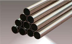
- Various grades of SS: SS 304 and SS 316
- Plastic Pipes: These are used for transporting actively corrosive fluids, and is especially useful for handling corrosive or hazardous gases and dilute mineral acids. Plastics are used in three ways as all plastic pipe, as filled plastic materials (Glass fiber reinforced, carbon filled, etc.), and as lining or coating material. Plastic pipe is made from Polypropylene, Polyethylene, Polybutylene, Poly vinylchloride, Acrylonitrile Butadiene Styrene, Cellulose Acetate-butyrate, Polyolefins, and Polyesters. Pipe made from Polyester and Epoxy resins is frequently glass fiber reinforced (FRP) and commercial product of this type have good resistance to wear and chemical attack.
- Glass: Generally, Borosilicate glass is used for pipes and fittings. All glass piping is used for its chemical resistance, cleanliness and transparency. Glass pipe is subjected to cracking, often found in glass lined pipes and vessels subjected to repeated thermal stresses. Pipes, fittings and hardware are available both for process piping and for drainage. Process lines of 25, 40, 50, 80, 100 and 150 mm NB are readily available, with 200oC as the maximum operating temperature and pressure range up to 4 kg/cm2. (for 25 to 80 mm NB), 3.5 kg/cm2. (for 100 mm NB) and 2.5 kg/cm2. (for 150 mm NB)
- Lining and Coating: Lining and coating carbon steel pipe with a material able to withstand chemical attack permits its use to carry corrosive fluids. Lengths of lined pipes and fittings joined by flanges, and elbows, tees etc, are available readily flanged. Lining like rubber can be applied after fabricating the pipe, but pipe is often pre-lined. Lining of various rubbers, plastics, metals and vitreous material is available. Coating is made from Plastics like Poly-propylene, Poly-ethylene, Poly-butylene, Poly-vinylchloride, Acrylonitrile Butadiene Styrene, Poly-olefins, and Poly-esters. Carbon Steel pipe coated with zinc, by immersion into molten zinc (hot-dip galvanized) is used for conveying drinking water, instrument air and various other fluids. Rubber and Basalt lining is often used to handle abrasive fluids.
Reinforcements: This is used for straight run pipes as well as for branch connections.
- On Straight Pipe: If a butt-weld, joining two sections of straight pipe is subject to unusual external stress, it may be reinforced by addition of a sleeve, which is a pipe cut at the seams in two parts. The Code applicable to piping should be referred for reinforcement. Reinforcing pieces are usually provided with a small hole to vent gases produced by welding, which would otherwise get trapped. A vent hole also serves to indicate any leak in the weld.
- On Branch Connections: It is addition of extra metal at a branch connection made from a pipe or vessel wall. The added metal compensates for structural weakening due to the hole. Stub-ins may be reinforced with regular or wrap-around saddles. Rings made from pipe stock are used to reinforce branches made with welded laterals and butt welded connections to vessels. Small welded connections may be reinforced by adding extra metal to the joint.
Methods of Pipe Joining: There are five methods of joining pipes to each other. These are Butt-Welded, Socket Welded, Screwed, Bolted Flanges and Bolted Quick Couplings.
- Butt Welded Pipes: These are used for most of the process, utility and service piping. If welding is not properly done, intruding material may affect flow. The end of the pipe is first beveled. Fittings are similarly beveled by the manufacturer. The two parts are aligned, properly gapped, tack welded, and the continuous weld is made to complete the joint. Pipe lines of 50 mm NB and larger are usually butt welded, this being the most economic and leak proof way of joining larger diameter piping. Usually such lines are sub-contracted to a piping fabricator for pre-fabrication in sections, termed as spools, which are then transported to the site. Butt weld fittings are used in these lines.
- Socket-Welded Pipes: These are used for pipelines conveying flammable, toxic or expensive materials, where no leakage can be permitted. Socket welding is easier to align on small lines than butt welding. Tack welding is not necessary. No weld metal can enter the bore. Joint will not leak, when properly made. A small gap between pipe and fitting may hold liquid in it. To make the joint, pipe is finished flat. It is located in the fitting, valve or flange etc., and a continuous fillet weld is made around the circumference. Pipe lines 40 mm NB and smaller are usually socket welded and are normally field run by the piping contractor from General Arrangement Drawings. These have socket welding fittings.
- Screwed Pipes: Pipe lines 40 mm NB and smaller can have screwed joints but these joints can leak. These should not be used for flammable or corrosive liquids. These can be easily made on site from pipes and fittings. It minimizes fire hazard when installing these as no welding work is involved. Not good for erosion, crevice corrosion, shock or vibration or at very high temperatures. Seal welding may be necessary. Strength of the pipe is reduced, as forming the screw thread reduces the wall thickness. These are field run by piping contractor.
- Bolted Flanged Pipes: These are expensive and for the most part are used to mate with flanged vessels, equipments, valves, and for process lines which may require periodic cleaning. Flanged joints are made by bolting together two flanges with a gasket between them to provide a seal.
- Bolted Quick Couplings: Connections of this type may be suitable for either permanent or temporary use depending on the joint and gasket, and service conditions. Piping can be done rapidly with these, and these are useful for making repairs to lines, for constructing short-run process installations such as pilot plants and for process modifications.
PIPE DIMENSIONS AND WEIGHTS AS PER ANSI B 36.10
| NB of PIPE
| OD of PIPE
| Wall Thickness, mm
| Weight per meter, Kg
| Weight Class
| Schedule
|
| 8
| 10.3
| 1.73 |
0.37 |
STD |
40 |
| 2.41 |
0.47 |
XS |
80 |
| NB of PIPE
| OD of PIPE
| Wall Thickness, mm
| Weight per meter, Kg
| Weight Class
| Schedule
|
| 10
| 13.7
| 2.24 |
0.63 |
STD |
40 |
| 3.02 |
0.8 |
XS |
80 |
| NB of PIPE
| OD of PIPE
| Wall Thickness, mm
| Weight per meter, Kg
| Weight Class
| Schedule
|
| 12
| 17.1
| 2.31 |
0.84 |
STD |
XS |
| 3.2 |
1.1 |
XS |
80 |
| NB of PIPE
| OD of PIPE
| Wall Thickness, mm
| Weight per meter, Kg
| Weight Class
| Schedule
|
| 15
| 21.3
| 2.77 |
1.27 |
STD |
40 |
| 3.73 |
1.62 |
XS |
80 |
| 4.78 |
1.95 |
... |
160 |
| 7.47 |
2.55 |
XXS |
... |
| NB of PIPE
| OD of PIPE
| Wall Thickness, mm
| Weight per meter, Kg
| Weight Class
| Schedule
|
| 20
| 26.7
| 2.87 |
1.69 |
STD |
40 |
| 3.91 |
2.2 |
XS |
80 |
| 5.56 |
2.9 |
... |
160 |
| 7.82 |
3.64 |
XXS |
... |
| NB of PIPE
| OD of PIPE
| Wall Thickness, mm
| Weight per meter, Kg
| Weight Class
| Schedule
|
| 25
| 33.4
| 3.38 |
2.5 |
STD |
40 |
| 4.55 |
3.24 |
XS |
80 |
| 6.35 |
4.24 |
... |
160 |
| 9.09 |
5.45 |
XXS |
... |
| NB of PIPE
| OD of PIPE
| Wall Thickness, mm
| Weight per meter, Kg
| Weight Class
| Schedule
|
| 32
| 42.2
| 3.56 |
3.39 |
STD |
40 |
| 4.85 |
4.47 |
XS |
80 |
| 6.35 |
5.61 |
... |
160 |
| 9.7 |
7.77 |
XXS |
... |
| NB of PIPE
| OD of PIPE
| Wall Thickness, mm
| Weight per meter, Kg
| Weight Class
| Schedule
|
| 40
| 48.3
| 3.68 |
4.05 |
STD |
40 |
| 5.08 |
5.41 |
XS |
80 |
| 7.14 |
7.25 |
... |
160 |
| 10.16 |
9.56 |
XXS |
... |
| NB of PIPE
| OD of PIPE
| Wall Thickness, mm
| Weight per meter, Kg
| Weight Class
| Schedule
|
| 50
| 60.3
| 3.91 |
5.44 |
STD |
40 |
| 5.54 |
7.48 |
XS |
80 |
| 8.74 |
11.11 |
... |
160 |
| 11.07 |
13.44 |
XXS |
... |
| NB of PIPE
| OD of PIPE
| Wall Thickness, mm
| Weight per meter, Kg
| Weight Class
| Schedule
|
| 65
| 73.0
| 5.16 |
8.63 |
STD |
40 |
| 7.01 |
11.41 |
XS |
80 |
| 9.52 |
14.9 |
... |
160 |
| 14.02 |
20.39 |
XXS |
... |
| NB of PIPE
| OD of PIPE
| Wall Thickness, mm
| Weight per meter, Kg
| Weight Class
| Schedule
|
| 80
| 88.9
| 3.18 |
6.72 |
... |
... |
| 3.96 |
8.29 |
... |
... |
| 4.78 |
9.92 |
... |
... |
| 5.49 |
11.29 |
STD |
40 |
| 6.35 |
12.93 |
... |
... |
| 7.14 |
14.4 |
... |
... |
| 7.62 |
15.27 |
XS |
80 |
| 11.13 |
21.35 |
... |
160 |
| 15.24 |
27.68 |
XXS |
... |
| NB of PIPE
| OD of PIPE
| Wall Thickness, mm
| Weight per meter, Kg
| Weight Class
| Schedule
|
| 90
| 101.6
| 3.18 |
7.72 |
... |
... |
| 3.96 |
9.53 |
... |
... |
| 4.78 |
11.41 |
... |
... |
| 5.74 |
13.57 |
STD |
40 |
| 6.35 |
14.92 |
... |
... |
| 7.14 |
16.63 |
... |
... |
| 8.08 |
18.63 |
XS |
80 |
| NB of PIPE
| OD of PIPE
| Wall Thickness, mm
| Weight per meter, Kg
| Weight Class
| Schedule
|
| 100
| 114.3
| 3.18 |
8.71 |
... |
... |
| 3.96 |
10.78 |
... |
... |
| 4.78 |
12.91 |
... |
... |
| 5.56 |
14.91 |
... |
... |
| 6.02 |
16.07 |
STD |
40 |
| 6.35 |
16.9 |
... |
... |
| 7.14 |
18.87 |
... |
... |
| 7.92 |
20.78 |
... |
... |
| 8.56 |
22.32 |
XS |
80 |
| 11.13 |
28.32 |
... |
120 |
| 13.49 |
33.54 |
... |
160 |
| 17.12 |
41.03 |
XXS |
... |
| NB of PIPE
| OD of PIPE
| Wall Thickness, mm
| Weight per meter, Kg
| Weight Class
| Schedule
|
| 125
| 141.3
| 3.96 |
13.41 |
... |
... |
| 4.78 |
16.09 |
... |
... |
| 5.56 |
18.61 |
... |
... |
| 6.55 |
21.77 |
STD |
40 |
| 7.14 |
23.62 |
... |
... |
| 7.92 |
26.05 |
... |
... |
| 8.74 |
28.57 |
... |
... |
| 9.52 |
30.94 |
XS |
80 |
| 12.7 |
40.28 |
... |
120 |
| 15.88 |
49.11 |
... |
160 |
| 19.05 |
57.43 |
XXS |
... |
| NB of PIPE
| OD of PIPE
| Wall Thickness, mm
| Weight per meter, Kg
| Weight Class
| Schedule
|
| 150
| 168.3
| 4.78 |
19.27 |
... |
... |
| 5.56 |
22.31 |
... |
... |
| 6.35 |
25.36 |
... |
... |
| 7.11 |
28.26 |
STD |
40 |
| 7.92 |
31.32 |
... |
... |
| 8.74 |
34.39 |
... |
... |
| 9.52 |
37.28 |
... |
... |
| 10.97 |
42.56 |
XS |
80 |
| 14.27 |
54.2 |
... |
120 |
| 18.26 |
67.56 |
... |
160 |
| 21.95 |
79.22 |
XXS |
... |
| NB of PIPE
| OD of PIPE
| Wall Thickness, mm
| Weight per meter, Kg
| Weight Class
| Schedule
|
| 200
| 219.1
| 4.78 |
25.26 |
... |
... |
| 5.16 |
27.22 |
... |
... |
| 5.56 |
29.28 |
... |
... |
| 6.35 |
33.31 |
... |
20 |
| 7.04 |
36.31 |
... |
30 |
| 7.92 |
41.24 |
... |
... |
| 8.18 |
42.55 |
STD |
40 |
| 8.74 |
45.34 |
... |
... |
| 9.52 |
49.2 |
... |
... |
| 10.31 |
53.08 |
... |
60 |
| 11.13 |
57.08 |
... |
... |
| 12.7 |
64.64 |
XS |
80 |
| 15.09 |
75.92 |
... |
100 |
| 18.26 |
90.44 |
... |
120 |
| 20.62 |
100.92 |
... |
140 |
| 22.22 |
107.88 |
XXS |
... |
| 23.01 |
111.27 |
... |
160 |
| NB of PIPE
| OD of PIPE
| Wall Thickness, mm
| Weight per meter, Kg
| Weight Class
| Schedule
|
| 250
| 273.0
| 4.78 |
31.62 |
... |
... |
| 5.16 |
34.08 |
... |
... |
| 5.56 |
36.67 |
... |
... |
| 6.35 |
41.75 |
... |
20 |
| 7.09 |
46.49 |
... |
... |
| 7.8 |
51.01 |
... |
30 |
| 8.74 |
56.96 |
... |
... |
| 9.27 |
60.29 |
STD |
40 |
| 11.13 |
71.87 |
... |
... |
| 12.7 |
81.52 |
XS |
60 |
| 15.09 |
95.97 |
... |
80 |
| 18.26 |
114.7 |
... |
100 |
| 21.44 |
133 |
... |
120 |
| 25.4 |
155.09 |
XXS |
140 |
| 28.57 |
172.21 |
... |
160 |
| NB of PIPE
| OD of PIPE
| Wall Thickness, mm
| Weight per meter, Kg
| Weight Class
| Schedule
|
| 300
| 323.8
| 5.16 |
40.55 |
... |
... |
| 5.56 |
43.63 |
... |
... |
| 6.35 |
49.71 |
... |
20 |
| 7.14 |
55.75 |
... |
... |
| 7.92 |
61.69 |
... |
... |
| 8.38 |
65.18 |
... |
30 |
| 8.74 |
67.9 |
... |
... |
| 9.52 |
73.78 |
STD |
... |
| 10.31 |
79.7 |
... |
40 |
| 11.13 |
85.82 |
... |
... |
| 12.7 |
97.43 |
XS |
... |
| 14.27 |
108.92 |
... |
60 |
| 17.48 |
132.04 |
... |
80 |
| 21.44 |
159.86 |
... |
100 |
| 25.4 |
186.91 |
XXS |
120 |
| 28.57 |
208 |
... |
140 |
| 33.32 |
238.68 |
... |
160 |
| NB of PIPE
| OD of PIPE
| Wall Thickness, mm
| Weight per meter, Kg
| Weight Class
| Schedule
|
| 350
| 355.6
| 5.33 |
46.04 |
... |
... |
| 5.56 |
47.99 |
... |
... |
| 6.35 |
54.69 |
... |
10 |
| 7.14 |
61.35 |
... |
... |
| 7.92 |
67.9 |
... |
20 |
| 8.74 |
74.76 |
... |
... |
| 9.52 |
81.25 |
STD |
30 |
| 11.13 |
94.55 |
... |
40 |
| 11.91 |
100.94 |
... |
... |
| 12.7 |
107.39 |
XS |
... |
| 15.09 |
126.71 |
... |
60 |
| 19.05 |
158.1 |
... |
80 |
| 23.83 |
194.96 |
... |
100 |
| 27.79 |
224.65 |
... |
120 |
| 31.75 |
253.56 |
... |
140 |
| 35.71 |
281.7 |
... |
160 |
| 50.8 |
381.83 |
... |
... |
| 53.97 |
401.44 |
... |
... |
| 55.88 |
413.01 |
... |
... |
| 63.5 |
457.4 |
... |
... |
| NB of PIPE
| OD of PIPE
| Wall Thickness, mm
| Weight per meter, Kg
| Weight Class
| Schedule
|
| 400
| 406.4
| 5.56 |
54.96 |
... |
... |
| 6.35 |
62.64 |
... |
10 |
| 7.14 |
70.3 |
... |
... |
| 7.92 |
77.83 |
... |
20 |
| 8.74 |
85.71 |
... |
... |
| 9.52 |
93.17 |
STD |
30 |
| 11.13 |
108.49 |
... |
... |
| 11.91 |
115.86 |
... |
... |
| 12.7 |
123.3 |
XS |
40 |
| 16.66 |
160.12 |
... |
60 |
| 21.44 |
203.53 |
... |
80 |
| 26.19 |
245.56 |
... |
100 |
| 30.96 |
286.64 |
... |
120 |
| 36.53 |
333.19 |
... |
140 |
| 40.49 |
365.35 |
... |
160 |
| NB of PIPE
| OD of PIPE
| Wall Thickness, mm
| Weight per meter, Kg
| Weight Class
| Schedule
|
| 450
| 457.2
| 6.35 |
70.60 |
... |
10 |
| 7.14 |
79.24 |
... |
... |
| 7.92 |
87.75 |
... |
20 |
| 8.74 |
96.66 |
... |
... |
| 9.52 |
105.1 |
STD |
... |
| 10.31 |
113.62 |
... |
... |
| 11.13 |
122.43 |
... |
30 |
| 11.91 |
130.78 |
... |
... |
| 12.7 |
139.2 |
XS |
... |
| 14.27 |
155.87 |
... |
40 |
| 19.05 |
205.83 |
... |
60 |
| 23.83 |
254.67 |
... |
80 |
| 29.36 |
309.76 |
... |
100 |
| 34.92 |
363.64 |
... |
120 |
| 39.67 |
408.45 |
... |
140 |
| 45.24 |
459.59 |
... |
160 |
| NB of PIPE
| OD of PIPE
| Wall Thickness, mm
| Weight per meter, Kg
| Weight Class
| Schedule
|
| 500
| 508.0
| 6.35 |
78.55 |
... |
10 |
| 7.14 |
88.19 |
... |
... |
| 7.92 |
97.67 |
... |
... |
| 8.74 |
107.6 |
... |
... |
| 9.52 |
117.02 |
STD |
20 |
| 10.31 |
126.53 |
... |
... |
| 11.13 |
136.37 |
... |
... |
| 11.91 |
145.7 |
... |
... |
| 12.7 |
155.12 |
XS |
30 |
| 15.09 |
183.42 |
... |
40 |
| 20.62 |
247.83 |
... |
60 |
| 26.19 |
311.17 |
... |
80 |
| 32.54 |
381.53 |
... |
100 |
| 38.1 |
441.49 |
... |
120 |
| 44.45 |
508.11 |
... |
140 |
| 50.01 |
564.81 |
... |
160 |
| NB of PIPE
| OD of PIPE
| Wall Thickness, mm
| Weight per meter, Kg
| Weight Class
| Schedule
|
| 600
| 609.6
| 6.35 |
94.46 |
... |
10 |
| 7.14 |
106.08 |
... |
... |
| 7.92 |
117.51 |
... |
... |
| 8.74 |
129.5 |
... |
... |
| 9.52 |
140.8 |
STD |
20 |
| 10.31 |
152.37 |
... |
... |
| 11.13 |
164.26 |
... |
... |
| 11.91 |
175.54 |
... |
.... |
| 12.7 |
186.94 |
XS |
... |
| 14.27 |
209.5 |
... |
30 |
| 17.48 |
255.24 |
... |
40 |
| 23.83 |
344.23 |
... |
... |
| 24.61 |
355.02 |
... |
60 |
| 30.96 |
441.78 |
... |
80 |
| 38.89 |
547.33 |
... |
100 |
| 46.02 |
639.58 |
... |
120 |
| 52.37 |
719.63 |
... |
140 |
| 59.54 |
807.63 |
... |
160 |
Close