 |
Satish Lele lelepiping@gmail.com |
View this page as YouTube Video Presentation
|
A boiler is a closed vessel in which water is heated. The heated or vaporized fluid exits the boiler for use in various processes or heating applications. The pressure vessel in a boiler is usually made of steel or alloy steel. Stainless steel is virtually prohibited by the ASME Boiler Code for use in wetted parts of modern boilers, but is used often in super heater sections that will not be exposed to liquid boiler water. There are two main types of boilers. Fire tube boiler, is one where, water partially fills a boiler barrel with a small volume left above to accommodate the steam. This type of boiler not used in industry. In Water-tube boiler, the water tubes are arranged inside a furnace in a number of possible configurations, often the water tubes connect large drums, the lower ones containing water and the upper ones, steam and water. In small boilers, such as a mono tube boiler, water is circulated by a pump through a succession of coils. This type generally gives high steam production rates, but less storage capacity than the above. Water tube boilers can be designed to exploit any heat source and are generally preferred in high pressure applications, since the high pressure water or steam is contained within small diameter pipes which can withstand the pressure with a thinner wall. Boiler is generally located in utility area, away from process plant. |
|
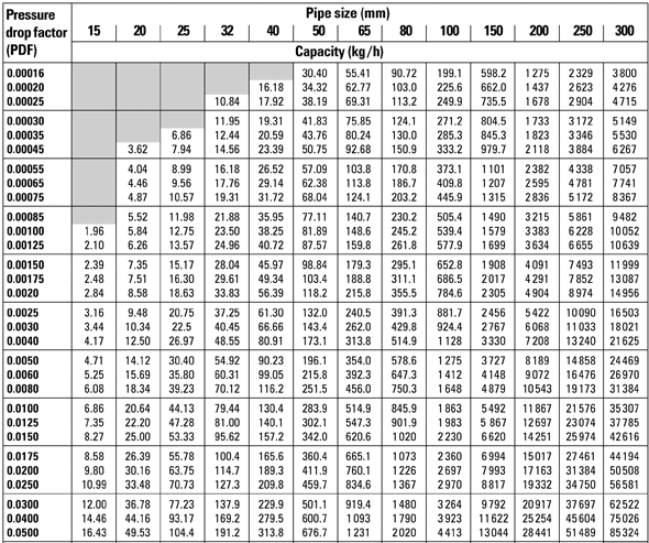
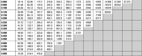
The use of steam in the piping business is extremely common and the efficient handling of steam lines is essential. The major consequence of running steam through piping is that as the pipeline cools, the steam loses heat and produces condensate which if left in the line will cause water hammer and subsequent damage to the piping system and / or equipment. Steam Pipes : Pipes for steam systems are commonly manufactured from carbon steel to ASME (ANSI) B 16.9 A106. The same material may be used for condensate lines, although copper tubing is preferred in some industries. For high temperature superheated steam mains, additional alloying elements, such as chromium and molybdenum, are included to improve tensile strength and creep resistance at high temperatures. Typically, pipes are supplied in 6 meter lengths. The pipes and fittings used are as per Boiler Regulation Laws (Indian Boiler Regulation Act in India). The pipes are of seamless construction and stamped for use as steam pipe. Sizing pipes based on velocity : The velocity is an important factor in sizing of steam pipes. If a reasonable velocity could be used for a particular fluid flowing through pipes, then velocity could be used as a practical sizing factor. As a general rule, a velocity of 25 to 40 meters / second is used when saturated steam is the medium. 40 meters / second should be considered as an extreme limit. Above this, noise and erosion will take place, particularly if the steam is wet. Even these velocities can be high in terms of their effect on pressure drop. In longer supply lines, it is often necessary to restrict velocities to 15 meters / second to avoid high pressure drops. It is recommended that pipelines over 50 m long are always checked for pressure drop, no matter what the velocity. |
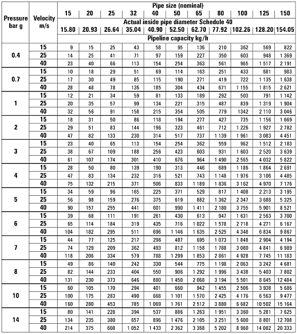
Pressure Drop Factor
|
Steam Piping Layout : Steam piping starts from stop valve of Steam Boiler, which is generally located on the top of the boiler. It is then carried to plant on Pipe Rack. On pipe rack, it is placed at the end. This helps in providing expansion loops. If the loops to be provided are above the pipe, the steam pipe is placed on upper rack. If a U loop is provided below the pipe, the pipe is located on lower rack. A shoe is provided to the pipe, where ever it rests on the structure. It helps in ease of insulation of the pipe. Shoe is prepared by cutting an I beam into 2 parts, and welded to pipe from lower side. Fiberglass sheets are the preferred insulation. Thickness of insulation depends on surface temperature of the pipe. An expansion loop is provided for every 8 meters of pipe length for a steam pipe having diameter
up to 100 mm NB or 4" NB. For sizes above this size, it is after every 4 meters or less. Generally, Gate, Globe and Plug valves are used to control flow of steam. Inside the plant, pipe is run close to wall or steel structure for proper support. The direction of pipe is changed by 90 degrees, every 8 meters (or 4 meters or less). A steam flow control station, which is placed firmly on the ground, is placed near the equipment. Condensate Piping : The condensate from the equipment, is removed by condensate pipe. The size of condensate pipe is smaller than steam pipe. A steam trap is connected to the end of pipe. Condensate coming out of steam trap, is collected in condensate tank and sent to Boiler house. The flash steam from condensate tank, is used in the plant for heating purposes. Steam Trap : The first function of any steam trap is to remove air and non-condensable gases from the equipment to which it is assigned. If the air is not removed, steam will not be able to enter the equipment. Hence, heat transfer will not occur. If air is not removed as designed, you may get uneven heating among different components, poor steam distribution and possible corrosion. The next job of the trap is to close in the presence of steam. 1 lb of water at saturation conditions (15 psig and 250°F) contains 218 Btu; 1 lb of steam at the same pressure contains 1,163 Btu. Of that, 945 Btu are in the form of latent heat. That is to say, as the steam condenses into a liquid, it gives up its latent heat. You can see that much more energy can be removed from 1 lb of steam than from 1 lb of water. You do not want steam to leave the system or process before it gives up its latent energy. The last job of the trap is to drain condensate. As the steam gives up its latent heat, it changes phase from a vapor into a liquid. This liquid is called condensate. This condensate must be removed from the heat transfer equipment. If it’s not removed, then you have less heat transfer area for the steam, and possible water hammer, upstream of the trap. Consequently, that means less heat will be transferred.
|
Location:
Steam trap suppliers such as Armstrong and Spirax Sarco are extremely knowledgeable and offer excellent instructional information.
|
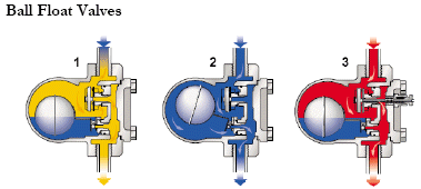
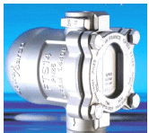
Ball float trap works in the following method
On start up a thermostatic air vent allows air to bypass the main valve.
As soon as the condensate reaches the trap, the lever mechanism opens the main valve. Hot condensate closes the air vent but continues to flow through the main valve.
When all condensate is removed, the float drops and closes the main valve, which remains at all times below the water level, ensuring that live steam is not wasted.
Inverted Bucket Traps : The inverted bucket is the most reliable steam trap operating principle known. The heart of its simple design is a unique leverage system that multiplies the force provided by the bucket to open the valve against pressure. Since the bucket is open at the bottom, it resists damage from water hammers, and wearing points are heavily reinforced for long life.

Inverted Bucket Trap works in the following method
As condensate reaches the trap it forms a water seal inside the body. The weight of the bucket keeps the valve off its seat. Condensate can then flow around the bottom of the bucket and out of the trap.
When steam enters the underside of the bucket, it gives buoyancy and the trap rises. This positions the lever mechanism such that main valve snaps shut.
The bucket will lose its buoyancy as the enclosed steam condenses and steam escapes through the vent hole. Once this happens the weight of the bucket will pull the valve off its seat and the cycle is then repeated.
Any air entering the trap will give the bucket buoyancy and close the valve and prevent condensate flow. The small vent hole in the bucket will bleed the air into the top of the trap.
Thermodynamic Trap : The thermodynamic trap is a robust steam trap with simple operation. The trap operates by means of the dynamic effect of flash steam as it passes through the trap.

Thermodynamic Trap works in the following method
On start up, upstream pressure raises the disc, and cooled condensate plus air is immediately discharged.
Hot condensate flowing through the trap releases flash steam at high velocity which creates a low pressure area under the disc, drawing it towards the seat.
At the same time the pressure of the flash steam builds up in the chamber above the disc forcing it down against the pressure of the incoming condensate until it sits on the inner ring and closes the inlet. The disc also sits on the outer ring and traps the pressure in the chamber.
Pressure in the chamber decreases as the flash steam condenses and the disc is raised by the incoming pressure. The cycle is then repeated.
Thermostatic Traps : There are two basic designs for the thermostatic steam trap, a bimetallic and a balanced pressure. Both designs use the difference in temperature between live steam and condensate or air to control the release of condensate and air from the steam line. In a thermostatic bimetallic trap it is common that an oil filled element expands when heated to close a valve against a seat. It may be possible to adjust the discharge temperature of the trap - often between 60oC and 100oC. This makes the thermostatic trap suited to get rid of large quantities of air and cold condensate at the start-up condition. On the other hand the thermostatic trap will have problems to adapt to the variations common in modulating heat exchangers.

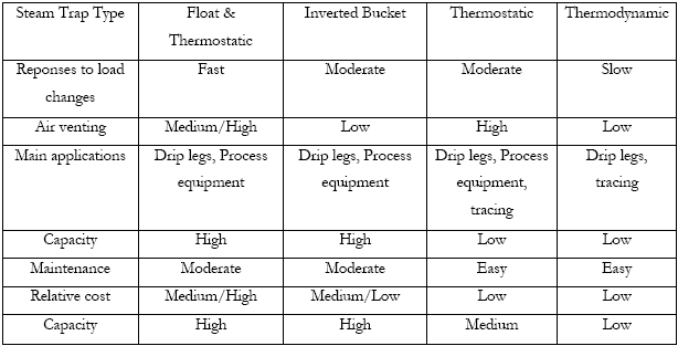
Steam Trap Selection
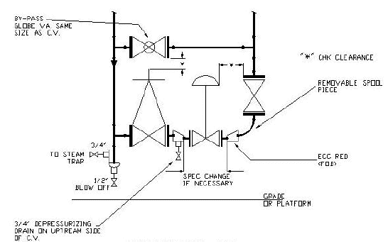
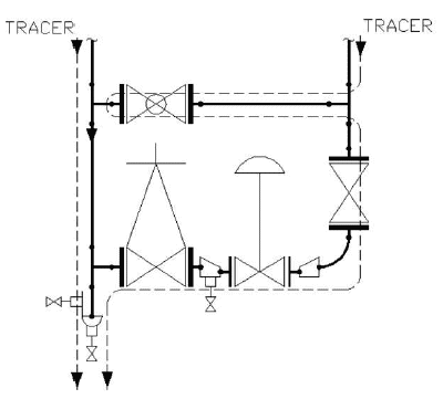
Steam Control Station : A typical Steam Control Station is shown below. It consists of 2 stop valves to block the flow, for removal of the control valve for repairs. A bypass valve is also provided, in case control valve is out of order. Every low point in a steam line must be trapped and steam control sets are no exception, the drip leg must be located upstream of the upstream block valve so it is still functioning while the flow is going through the bypass.
Steam Tracing : Pipelines carrying viscous fluids are frequently maintained at an elevated (or operating) temperature by means of steam tracers. These usually consist of one or more small bore steam lines running alongside the product line, the whole being covered in insulation. Steam tracing is also used as an alternate to electrical tracing in freeze protection of lines. The exact calculation of steam consumption is difficult, as it depends on:
The degree of contact between the two lines, and whether heat conducting pastes are used.
The temperature of the product.
The length, temperature and pressure drop along the tracer lines.
The ambient temperature.
Wind speed.
The emissivity of the cladding.

In practice, it is usually safe to assume that the tracer line simply replaces radiation losses from the product line itself. On this basis, the steam consumption of the tracer line may be taken as a running load being equal to the radiation loss from the product lines.
A steam tracing system consists of tracer lines separately fed from a steam supply header, each tracer terminating with a separate trap.
The best way to size a steam tracing header is to calculate the total cross section of all the tracers and to calculate the header size allowing the same flow area.
The rate at which condensate forms and fills the tracer determines the length of the tracer in contact with the line.
Expansion of the tracers must be considered and may be accommodated in horizontal piping by looping the tracer at elbows. Care must be taken that the expansion of the tracer does not cause damage to the insulation.
Schedule 80 carbon steel pipe, or copper or stainless steel tubing is used for tracers. Selection is based on steam pressure and required tracer size. Tracers are either 3/8” or 1/2” size with copper tubing being the most economical installation.
Run tracers parallel to and against the underside of the pipe to be heated.
Run a steam tracing sub-header to operating level and individual tracers should take off from the top of the header with an isolating valve provided.
Feed steam to the highest point of the system of lines to be traced, so that gravity will assist the flow of condensate to the traps and condensate header.
Provide unions at loops around flanges.
Do not provide a trap at every low point of a tracer (as in steam lines) but provide one at the end of the tracer.
Do not run more than one tracer to a trap.
If possible group supply sub-headers and condensate return headers and locate them at grade or on a platform.
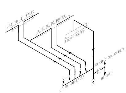
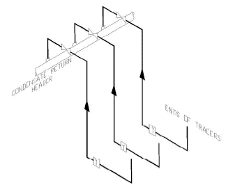
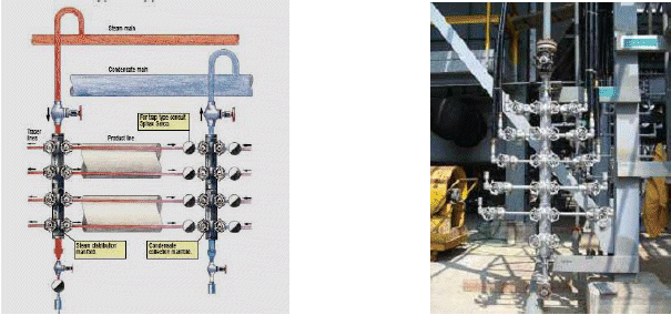
Pre-Manufactured Steam and Condensate Manifolds
Steam Tracing at a Steam Control Station
Steam Tracing and Manifolds
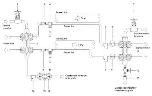
Manifolds on Non-Critical Tracing : The required components of non-critical tracing control with manifolds.
Isolation Valve to isolate the drain trap from the supply steam.
Steam Condensate Manifold to distribute steam to tracing lines.
Strainer to protect the control valve from detritus.
Temperature Control Valve to regulate the flow of steam through the tracer.
Spiratec Sensor Chamber to monitor the trap condition.
Steam Tracing Steam Trap to discharge condensate correctly.
Isolation Valve to isolate the drain trap from the condensate system.
Steam Condensate Manifold to collect condensate from tracing lines.
Strainer to protect the control valve from detritus.
Temperature Control Valve to regulate the flow of steam through the tracer.
Steam Tracing Steam Trap to discharge condensate correctly.
Isolation Valve to drain the condensate manifold.
Diffuser to diffuse the condensate when draining to grade.
Spiratec Sensor Chamber to monitor the trap condition.
Steam Tracing Steam Trap to discharge condensate correctly.
Pipeline Connector to allow quick trap change during maintenance.
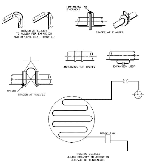
Typical Steam Tracing Application in an Oil Refinery
There are pipes running all round a typical oil refinery or chemical plant. These pipes carry crude oil, intermediate products and final products.
The largest pipes carry crude oil and are a meter in diameter. The heavier fractions of crude oil are either solid (bitumen and fuel oil) or thick viscous liquids (lube base stock and heavy gas oil). However, we have to move around the refinery through pipes and pumps. The only way to do this is to keep them hot.
Hot oil is less viscous than cold oil - i.e. it is thinner and flows more easily. When the fractions come out of the distillation column, they are already hot. However, they would soon cool down in normal pipes, clogging up pumps and the pipes themselves. So they have to be kept hot.
We do this using special pipes with steam tracers. The tracer is a pipe that runs alongside the oil pipe. It carries pressurized steam at up to 270°C. The assembly is then wrapped in thick insulation to reduce losses by conduction. This is covered in a shiny, metallic jacket that reduces the radiation (shiny surfaces radiated less than dull, black surfaces).
Different pipes have to be kept at different temperature. A pipe carrying bitumen is kept at 180°C using a steam tracer at 270°C. Sometimes, the tracer pipe runs down the middle of the pipe to keep it at such a high temperature. Other products are kept at more like 80°C using a steam tracer at 180°C.
The steam tracer keeps the product hot rather than heating it. It has already been heated in the furnace before distillation.
Even with all the insulation, the oil and the steam cool down as they run through the pipe. So most steam tracers are only about 150 meters long. One end is connected to the steam main that runs around the site and the other end passes out into the atmosphere where the cooled steam condenses. As one pipe passes out, a new pipe is fed into the lagging with fresh, hot steam.
Jacketed and Gut-Line Steam Tracing Systems : Jacketed and gut-line steam-tracing systems of this era were simply extended versions of the age-old double pipe heat exchanger. In this system, one of the process streams contains flowing steam and the other stream is the process fluid which requires temperature maintenance. The inner pipe contains the process fluid and the steam flows through the outer pipe. Steam enters at the top and condensate is drained through a nozzle at the bottom of the outer pipe. The distance between take offs depend on the rate of condensation. A slope of 1” every 10’ – 20” is required to aid in condensate removal.
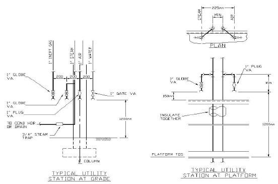
Hose Stations : The purpose of hose stations is to provide the plant with facilities to clean equipment and hose floors. The lines are steam, air and possibly water and inert gas. The piping to the hose station is permanent and from the station to the local would be a flexible hose. Hose Stations comprising of all services (water, steam, air possibly inert gas) are located at pipe rack columns so as to give coverage of whole unit at grade using 15 meters long hoses. Air and steam connections are placed at tower platforms such that these services are available by hose at each manhole. Thus one station may serve more than one platform by dropping the hose down from a station above. Horizontal Drum platforms are served from the yard (pipe rack) hose stations. In general most companies will have their own configuration for hose stations. Figure shows a couple of typical hose station installations. Firewater is run separately from an independent water supply.
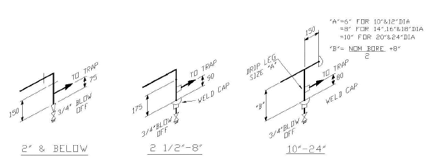
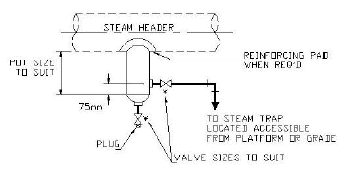 All steam piping systems must be designed so as to remove condensate from the steam line as soon as possible by the use of steam traps and drip legs. Drip legs collect condensate and are located at all low points in steam lines and at intervals in horizontal piping. A steam trap is connected to the drip leg and will open to allow the condensate to escape, then will close when it senses steam thereby not allowing any steam to escape from the line. Strainers must be provided upstream of the steam trap to prevent any scale or grit from entering the trap and causing them to stick in an open position. Some traps have built in strainers.
 to get all the information as a eBook
